
Inertial Navigation Systems (INS) – An Introduction
Share:
Published on:
Table of Contents
- Definition of an Inertial Navigation System (INS)
- Inertial Sensors Used in an Inertial Navigation System (INS)
- How do Inertial Navigation Systems (INS) Work?
- AI-Based Filtering Applied to Inertial Navigation Systems (INS) – Why and How
Definition of an Inertial Navigation System (INS)
An inertial navigation system, commonly known as an INS, is an electronic system that uses a variety of environmental sensors that are able to detect and measure the change in motion of an object. Using sensor data, an inertial navigation system can determine the position of the vehicle or object relative to its starting point – this is known as dead-reckoning.
Inertial Sensors Used in an Inertial Navigation System (INS)
Inertial Sensors
There are a number of types of sensors used in inertial navigation systems, however, the two primary types are accelerometers and gyroscopes.
Accelerometers can measure changes in linear velocity. As most objects can move in three-dimensional space, it is typical to use three accelerometers mounted orthogonally; that is, the axis of each accelerometer is at 90 ° to the others. They are usually given the labels of X-axis, Y-axis and Z-axis.
Gyroscopes measure rotational velocity, and again, as most objects are free to rotate in three-dimensional space, using three gyroscope axes is typical. They are also mounted on the object orthogonally, and aligned as best as possible with the three accelerometer axes.
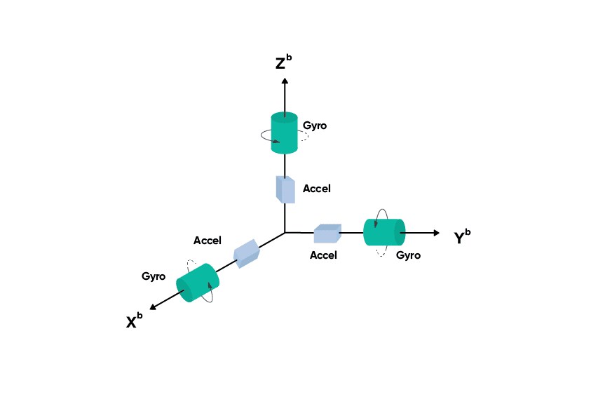
Image depicting the accelerometers and gyroscopes in the three axes of movement. Each accelerometer and gyroscope is positioned at 90 ° to the others (orthogonally).
A typical INS will have other in-built sensors or connected equipment to provide a more comprehensive dataset that is broader than motion alone, such as:
- GNSS receivers simultaneously receive and decode signals from multiple navigation satellites to provide three-dimensional position data. Using more than one receiver can aid in determining heading and orientation.
- Magnetometers detect and measure the strength and direction of the Earth’s magnetic fields. Three magnetometers are used to provide a three-dimensional orientation with respect to magnetic north.
- Pressure sensors measure external pressure. For example, a water pressure sensor for determining depth in underwater applications and an air pressure sensor (barometer) for determining altitude.
Inertial Measurement Unit (IMU)
In many modern inertial navigation systems, inertial sensing is performed by a module known as an “inertial measurement unit” (IMU), sometimes also called an inertial reference unit (IRU) or motion reference unit (MRU) . The IMU outputs raw motion data that is used by other parts of the INS, typically in conjunction with a GNSS input and perhaps other sensors. For more information on the IMU, read the “Inertial measurement unit (IMU) – an introduction” article.
Inertial Frames of Reference
It is important to understand the concept of frames of reference when measuring the motion of an object. To obtain accurate motion data, inertia must be measured within the constraints of an inertial frame of reference (also called “inertial reference frame”). This can be explained using Newton’s law of inertia.
The law of inertia states that an object at rest remains at rest, or an object in motion remains moving at the same velocity unless acted upon by an external force. The inertia created by external forces on an object within an inertial frame of reference can be measured because the reference frame is not accelerating. If the reference frame is also accelerating, then other forces come into play that affects the inertial measurement.
Typically, we use the Earth as an inertial reference frame, even though it is experiencing acceleration that causes it to spin on its axis and to orbit the Sun, which is also moving and so on. Fortunately, the complex mathematics required to use a non-inertial reference frame as an inertial frame of reference is taken care of by the navigation system, so its output can be considered as a record of motion of an object as though moving in 3D space and not being acted upon by other forces, such as gravity.
How do Inertial Navigation Systems (INS) Work?
To understand how inertial navigation systems work, it is useful to consider a train on a level, straight piece of track. Movement of the train is constrained – it can go only forward or backward. It cannot go up or down, left or right, and it cannot rotate in any manner.
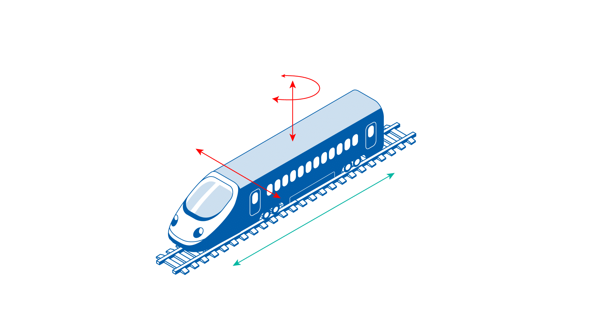
Image depicting a train on a straight track. The train is constrained in movement to forward/backward only
Measuring and Using Linear Acceleration
Using the train example, when the train is not moving, accelerometers measure the forwards / backwards axis (usually the X-axis) will be outputting a value of zero. When the train starts to move forward the accelerometer will detect the change in velocity and output the instantaneous acceleration values at a rapid rate, typically up to 1000 data points per second (1 kHz). Using the principles of integral calculus, it is possible to log the acceleration values over a period of time and calculate the distance the train has travelled. We can now, with confidence, locate the train along the track, but only relative to its starting position – we may or may not know the absolute position in the world where the train starting position is. To determine an absolute position using the surface of the Earth as a reference frame requires additional information – information that is typically provided by a GNSS/GPS receiver.
For vehicles not on a straight track, this method of measuring acceleration values, and by extension calculating relative position and distance from the starting point, can be extended from all three axes of motion using the accelerometers. The data from the accelerometers is combined into a single vector of travel using trigonometry.
Measuring and Using Rotational Acceleration
In reality, just about every vehicle type does not travel in straight lines, which means that the vehicle must rotate in some way to change direction. The gyroscopes are used to determine the direction of travel (heading) by measuring any rotation, and in which direction, on any of the three axes. Again, this direction is relative to the direction that the vehicle was in at the starting point, which may or may not be known absolutely. One common method of determining the absolute direction of travel is by using additional sensors such as magnetometers which will provide a heading value relative to the Magnetic North Pole.
By combining the distance travelled measurement from the accelerometers with the direction of travel from the gyroscopes, the position of the object, relative to the starting point can be determined with some degree of accuracy.
A Summary of Inertial Sensor Errors and Corrections
The value or worth of an inertial navigation system (INS) is often based on the accuracy of its inertial sensors. Some sensors are made better than others or have wider thresholds for operation than others, however, there is no such thing as a perfect sensor. For example, all sensors have inherent errors caused by physical limitations in the sensing technology or materials used. This means that all accelerometers and gyroscopes will output information that has an element of error.
Due to the fact that sensor measurement errors are inherent, the error accumulates the further the sensor travels from its starting position. For this reason, it must be assumed that the position information provided by an INS will have some degree of error. It is reasonable to say that generally the more you pay, the better quality and higher accuracy the sensors are. In terms of which INS to choose, the question often is determined by accuracy requirements and budget.
There are many factors that cause measurement errors and these cannot be avoided completely. There are, however, ways to mitigate some errors and not just by buying more expensive sensors. Methods of error correction include factory calibration and characterization of the sensors across the operating temperature range, and intelligent software-based sensor output filtering.
Inherent sensor errors at the hardware level cannot be eliminated and this has led to complex mathematical and statistical filter algorithms that are used in sensor data processing. These filters are designed to dynamically detect and remove biases (inherent errors) and errors caused by interference and noise, such as magnetic interference and vibration induced errors. Advanced Navigation has developed unique filter algorithms that take advantage of artificial intelligence (AI), which is a key emerging technology – read this article “How is AI revolutionising inertial navigation?” for more information.
Using GNSS for Absolute Position
As previously mentioned, using accelerometers and gyroscopes alone will provide position relative to the starting point only. To determine the position of the vehicle absolutely (or above or below) using the Earth’s surface as a frame of reference, it is common to use a GNSS/GPS receiver as an additional input into the INS.
Global Navigation Satellite System (GNSS), much like the sensors of an INS, is prone to errors such as timing, orbital and atmospheric interference that will affect the accuracy of navigation systems using the satellite information. This has led to the development of real-time kinematics (RTK) – these are mathematical techniques that are able to determine values to apply to correct satellite errors. Using RTK makes it possible to determine absolute position on Earth to within a few centimeters, sometimes even less. One of the advantages in using an intelligent software filter in an INS is that the GNSS is considered just another sensor and its data can be used to “tune” the other sensors in real-time to improve the output position accuracy.
To provide a simple example, let’s go back to our train on a level, straight track. An intelligent software filter will calculate the distance travelled using the accelerometer measurements and compare it, in real-time, with the distance travelled as determined by the GNSS/GPS receiver. If there is any discrepancy between the two results, the filter can “calibrate” the accelerometer to remove any biases or noise that may be present, say, from a vibration source for example. This ability of the filter is truly the heart and soul of an inertial navigation system and is what separates it from a simple integration calculation.
How an Inertial Navigation System (INS) Determines Heading
Finally, we can look at attaining an absolute heading determination from our inertial navigation system. The gyroscopes alone will provide a heading value that is relative only to your starting position and does not indicate where the object is heading relative to the North Pole. One common and low cost method of absolute heading determination is to use another sensor called a magnetometer.
A magnetometer measures the Earth’s magnetic field strength, and once again, three magnetometers are used, aligned orthogonally with the other sensors along the three axes. As with the accelerometers and gyroscopes, the magnetometer axes measurements are combined into a single vector.
When using a magnetometer for absolute heading determination, it is necessary to know what the Earth’s magnetic field strength is in your location. This information is known as the “world magnetic model” (WMM) and it is a three dimensional measurement of the Earth’s magnetic field strength at locations around the world, with a 50 km resolution. The WMM information is stored inside the inertial navigation system, and a comparison is made between the WMM value at that location and the measured value. Using trigonometry, the INS can determine how much the object has been rotated relative to the magnetic North Pole. From there, to determine the rotation (that is, heading) relative to what is known as True North, a value known as “declination” is added or subtracted.
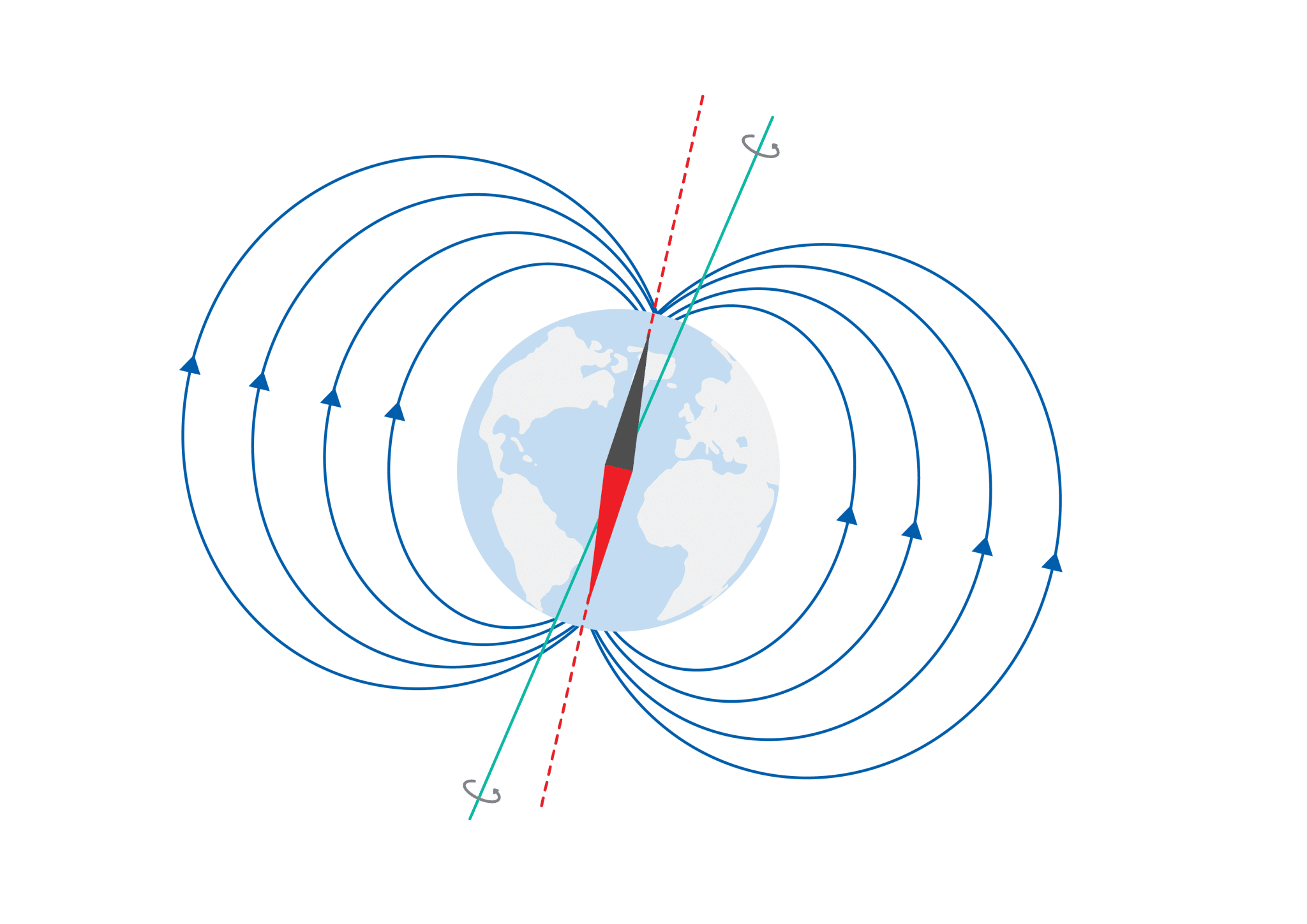
The red axis depicts “Magnetic North” as it is aligned with the Earth’s magnetic fields. The blue axis represents “True North” as it is the actual axis that the Earth spins around.
Note that to use the world magnetic model, the absolute position must be known, at least to within +/- 25 kms, so it is very common to use a GNSS/GPS receiver when using magnetometers.
Magnetometers are not ideal in every situation, however, as their measurements are very sensitive and therefore subject to interference, offset and distortion, by nearby ferrous objects or devices that generate magnetic fields such as electric motors. If the ferrous objects are fixed, relative to the sensor; for example, in a car, the interference can be calibrated out. If the ferrous objects are transient in nature; for example, driving over a steel plate, the interference can be intelligently filtered out. Unfortunately, if the ferrous object is close but not fixed in place, and is constantly present – imagine a nearby electric motor or a rotating piece of steel; using a magnetometer-based heading system may simply not be possible. In this case alternative heading sensors such as fibre-optic gyroscopes (FOG) that can find True North by measuring the rotation of the earth may be necessary.
AI-Based Filtering Applied to Inertial Navigation Systems (INS) – Why and How
Artificial intelligence (AI) is a rapidly expanding technology/methodology that is being adopted in many facets of industry to impart a level of automated decision-making into software. There is little doubt that AI is becoming a fundamental technology for automated and autonomous systems, electronics and delivering a growing variety of computer-based services. The Advanced Navigation filtering AI includes an artificial neural network (ANN), which is designed to resemble the interconnected neural pathways of a brain. The concept is based on a collection of nodes (“artificial neurons”) that are interconnected similarly to a biological system. Each neuron can transmit signals to other neurons, making cross-connections possible and affecting how connected neurons interact. For an inertial navigation system, you can think of a neuron to be an input or output of a sensor.
The integrated ANN is capable of signal processing that is significantly faster than navigation systems using Kalman filtering. Kalman filtering provides estimates for unknown variables that are primarily statistics-based. Faster processing means capturing sensor data more times per second – this results in finer granularity of the logged motion data and noticeably improved navigation performance.
AI improves sensor error detection and tracking when compared with Kalman filtering. Kalman filtering is somewhat limited due to applying basic linear constraints only to acceleration, velocity, and position. The Advanced Navigation AI-based algorithm applies dynamic constraints, including full physics models of vehicle motion. Using dynamic constraints as opposed to linear ones allows for better error detection and tracking, resulting in more reliable and higher accuracy motion data. The “learning” capabilities of the AI enable it to accumulate sensor error data and associated conditions during erroneous measurements and post-measurement corrections. The AI can then use this accumulated knowledge and apply sensor error offsets that are tailored to the prevailing conditions. The result of being able to interpret sensor data with regard to current conditions, historical corrections and their outcomes delivers higher navigational accuracy and improved dead-reckoning estimation as more nuanced sensor error data becomes available over time.
Recent Tech Articles
How Improved Positional Accuracy Can Transform Mining Excavation
Explore the new standard in absolute positioning for GNSS-denied environments. See how the Chimera Land LVS and INS pairing anchors real machine motion.
15 June 2026
Go to Article
High-Precision Navigation at Scale for Counter Drone Technology
Unlock precision for your kinetic effector on-the-move. Discover how Advanced Navigation delivers the stabilization and supply chain speed needed for scalable counter drone defense.
18 May 2026
Go to Article
Navigating the Future of Mining Operations
Discover how to improve product quality in manufacturing through Advanced Navigation's rigorous supply chain and exhaustive validation.
5 May 2026
Go to Article