
Inertial Navigation Systems
High accuracy MEMS and FOG-based Inertial Navigation Systems for precise orientation, positioning and navigation in GNSS-denied environments.
Enquire Now
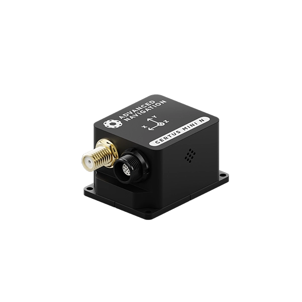
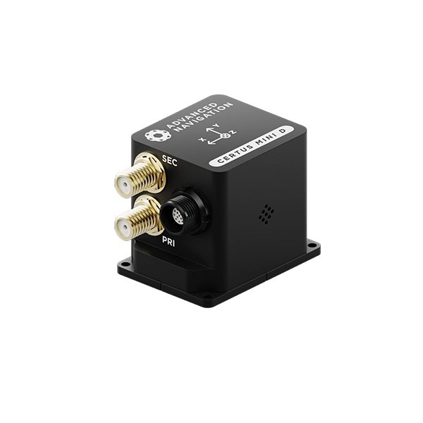
MEMS GNSS/INS
Ideal for applications where both precision navigation and low SWaP-C is necessary.


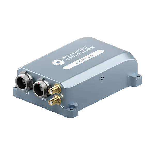
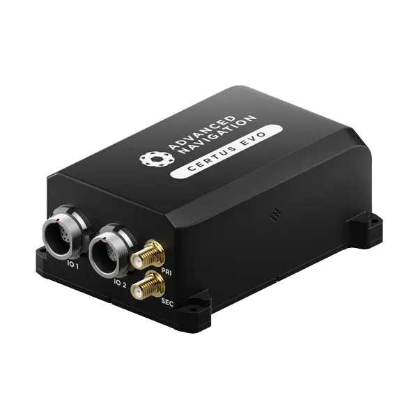
FOG GNSS/INS
Ideal for missions that demand long-term navigation in environments where GNSS is denied or disrupted.
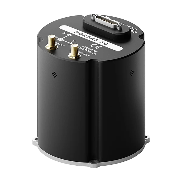
Horizontal Position Accuracy (GNSS RTK)
0.01 m
Roll & Pitch Accuracy
0.03 °
Heading Accuracy (Gyrocompass)
0.5 ° seclat
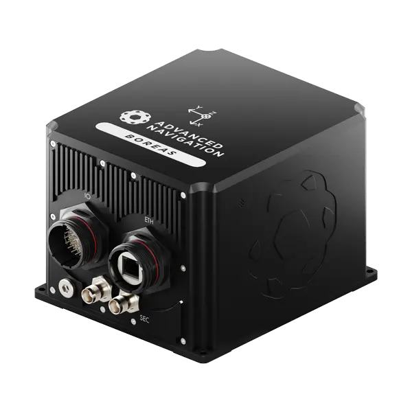
D70
D90
Roll & Pitch
0.01 °
0.005 °
Heading
0.1 ° seclat
0.01 ° seclat
Bias Instability
0.01 °/hr
0.001 °/hr
Position Accuracy
10 mm
10 mm
Technical Validation
Reliable Sensors
Advanced Navigation Inertial Navigation Systems contain reliable sensors that are each subject to an intensive 8-hour temperature-based calibration process. This provides the highest accuracy possible for each sensor class over the full operating temperature range from -40°C to 85°C.
Common Communication Protocol
All Advanced Navigation INS use a common communication protocol, enabling customers to extend their product range by moving up or down the accuracy spectrum without incurring re-engineering costs.
Vertically Integrated Manufacturing
Advanced Navigation’s vertically integrated manufacturing empowers its customers with supply chain security, speed-to-market, and quality assurance throughout the production process.
FAQs
What is an Inertial Navigation System?
An Inertial Navigation System, also known as an INS, is a navigation solution that measures changes in motion through inertial sensors in order to determine the velocity, orientation, and position of an object.
How does an Inertial Navigation System work? Does it include an inertial measurement unit and GNSS receiver?
The IMU within the Inertial Navigation System is composed of inertial sensors including accelerometers, gyroscopes, and often, magnetometers.
More details:
- Accelerometers are sensors that measure the acceleration of an object, tracking the changing velocity.
- Gyroscopes are rotation sensors that measure the changes in the angular velocity of an object.
- Magnetometers measure the strength and direction of the Earth’s magnetic field to determine the orientation with respect to the magnetic North Pole. The Inertial Navigation System will correct for the difference between the true north and the magnetic north. However, in most vehicles, the accuracy of a magnetometer is affected by magnetic interference sources.
Each of these sensors has its own limitations, which is why they work better when they are combined. By measuring these three sensors, the Inertial Navigation System is able to calculate any distance travelled and the heading.
By doing so, an Inertial Navigation System is capable of measuring:
- Pitch
- Roll
- Heading
An INS also incorporates a GNSS receiver which is used as an additional sensor. By doing so, it gives an absolute position rather than a relative position. An INS alone can determine a position relative to the inertial frame of reference, but combined with GNSS it can provide absolute position by accurately providing the global position.
INS and GNSS: What’s the difference?
An Inertial Navigation System is a self-contained system that doesn’t rely on satellite signals or base stations to calculate position.
A GNSS requires information from satellites to determine positioning. The use of GNSS is quite common in civilian, commercial, and defense applications with varying degrees of navigational accuracy. However, GNSS is subject to several modes of interference, including atmospheric disruption and multipathing. GNSS signals can also be lost due to obstructions like tunnels or intentional interference such as jamming and spoofing which is possible in military applications.
Working in tandem, the two navigation systems can be used to provide highly accurate positions, with an Inertial Navigation System able to calculate position should the vehicle enter a GNSS-denied environment, effectively improving GNSS navigation information.
What methods can be used to improve the performance of an INS (RTK, odometer, Air Data Unit, DVL)?
The accuracy of an INS can be further improved through the use of external aiding sensors. Input from these sensors is used as additional data for the sensor fusion algorithm to better estimate position, velocity and orientation.
The type of aiding sensors used with an INS will largely depend on the application. Some examples of aiding sensors include:
- Wheel Speed Sensor – Land Application – Measures vehicle speed through wheel rotation.
- OBDII Odometer – Land Application – Communicates with a vehicle onboard computer to provide vehicle speed to the INS.
- Air Data Unit – Air Application – Measures pitot airspeed and barometric altitude.
- Doppler Velocity Log (DVL) – Subsea Application – This is an acoustic sensor that estimates velocity relative to the sea floor.
All Advanced Navigation INS solutions can interface with a wide range of sensing technologies to improve performance.
What are the benefits of using an Inertial Navigation System?
Inertial Navigation Systems are proven solutions that provide position data. There are different types of Inertial Navigation Systems, ranging from lightweight MEMS (micro-electromechanical systems) to more dynamic fiber optic gyroscopes (FOG), and more advanced digital fiber optic gyroscopes (DFOG).
An Inertial Navigation System is particularly beneficial in a GNSS-denied (global navigation satellite system) environment. GNSS can be interfered with in underground environments like tunnels or underwater environments. GNSS signals can also be interfered with by way of multi-pathing or atmospheric interference. While this may be an inconvenience for navigation on a phone, for the likes of aerial surveying or defense applications, positioning requires no room for error.
This is why an Inertial Navigation System that integrates a GNSS is far more reliable, as an INS by nature mitigates the room for error a GNSS would experience alone. An Inertial Navigation System can operate effectively and accurately without communicating to a base station, making it well suited where GNSS is either susceptible to inaccuracies or isn’t available at all.
How accurate is an Inertial Navigation System?
There are many kinds of Inertial Navigation Systems, all of which have varying degrees of accuracy.
High-end INS that utilize fiber optic gyroscope (FOG) are accurate within centimeters and would be used for aerospace exploration, AUVs, and defense applications. Unlike GNSS, Inertial Navigation Systems are immune to jamming or spoofing as they don’t require references from external sources like satellites or base stations.
How is an INS calibrated and tested?
An INS calibration is important in ensuring that the sensor output results are accurate and repeatable within the specified operating conditions. Calibration is the process of comparing INS outputs with reference information and determining co-efficiency factors that need to be applied that the two match.
The output measurement of an INS can vary according to several factors, such as:
- Temperature – affects the output result of an INS when subject to a wide range of temperatures.
- Systematic error sources from accelerometers and gyroscopes such as:
- sensors bias
- sensor output scale factor
- sensor cross-axis sensitivity
- misalignment of sensor axis
- MEMS gyroscope G sensitivity
- Magnetic Field – Some INS units have a magnetometer sensor to help determine the heading. When an INS is subject to changes in the magnetic field (for example, by ferrous objects and magnets, which is known as static interference), the magnetometer output will vary. Typically, this type of error is calibrated once the INS has been installed in the final installation position on a vehicle to take into account all sources of static magnetic interference. All Advanced Navigation INS and AHRS systems have built-in magnetic calibration software to help counter this problem.
An INS can be calibrated to counter the abovementioned issues to produce accurate and repeatable results by utilizing equipment such as temperature chambers, leveling tables, rate tables and gimbals. All Advanced Navigation INS & AHRS products are calibrated, tested and checked for conformance to relevant industry standards before leaving the factory.