MEMS GNSS/INS
High-Accuracy MEMS-Based Inertial Navigation Systems
Advanced Navigation is a leading manufacturer of MEMS-based GNSS/INS. Our range of inertial navigation systems (INS) provides accurate position, velocity, acceleration, and orientation and are designed and built to withstand the most demanding conditions. The hardware platform combines temperature-calibrated accelerometers, gyroscopes, magnetometers, and pressure sensors with state-of-the-art RTK GNSS receivers. The software platform uses an AI-based algorithm unique to Advanced Navigation. This proprietary algorithm increases the INS accuracy and reliability by tracking sensor errors faster than traditional Kalman filtering.
This hardware-software combination enables our inertial navigation systems to deliver the highest performance for the lowest SWaP-C (Size, Weight, Power Consumption, and Cost)
Our GNSS INS use MEMS sensors that are rigorously tested and subject to an eight-hour temperature calibration process. This ensures the highest accuracy possible for each sensor class over the full operating temperature range (-40° C to 85° C).
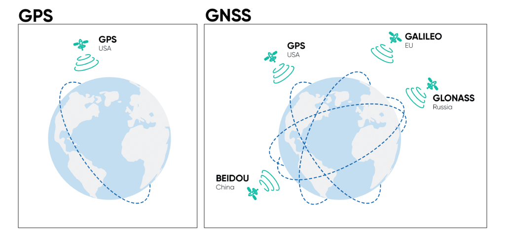
The GNSS receivers support all navigational satellite constellations, including GPS, GLONASS, GALILEO, BeiDou and QZSS.
The MEMS INS range covers accuracy grades from industrial to tactical. An internal filter rate of 1000 Hz ensures high dynamic performance in the most demanding applications.
Advanced Navigation applies vertical integration for both software and hardware engineering, design and manufacturing. This enables the two systems to be completely complimentary and enables our products to set new benchmarks for accurate and reliable navigation and positioning.
Advanced Navigation MEMS-based GNSS INS are ITAR-free, backed by a global support network, and suitable for both commercial and defence applications.
Our MEMS GNSS/INS Solutions
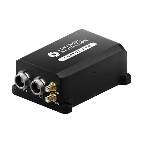
Our GNSS INS are available in both OEM and IP67-rated rugged housing versions. All Advanced Navigation INS is designed around a standardized communication protocol for streamlined integration. This enables customers to select different solutions and move up or down the accuracy spectrum of the product range without incurring re-engineering costs. This can drastically reduce implementation time and cost, and accelerate product testing and time to market.
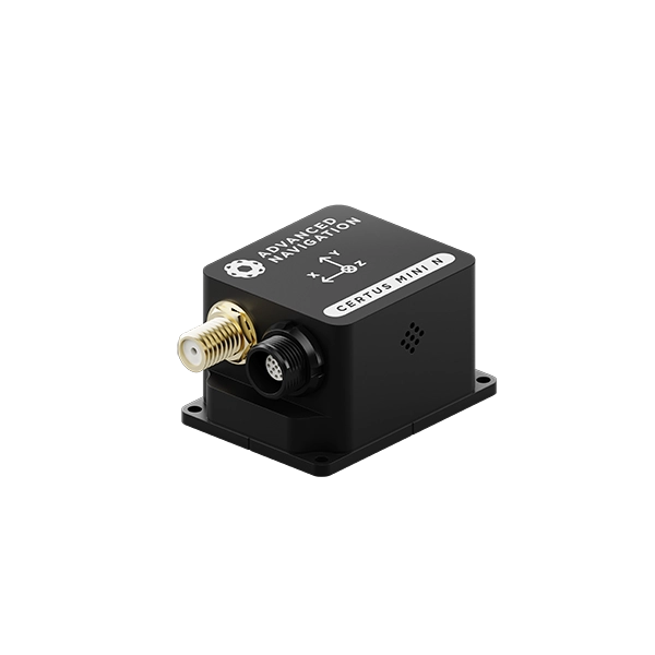

Navigation, single antenna
Roll & Pitch
0.1 °
Heading (Velocity)
0.2 °
RTK Positioning
10 mm
Output Data Rate
500 Hz
View Solution
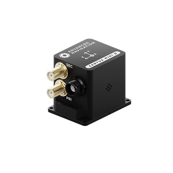
Dual-antenna Navigation
Roll & Pitch
0.1 °
Heading (GNSS)
0.1 °
RTK Positioning
10 mm
Output Data Rate
500 Hz
View Solution
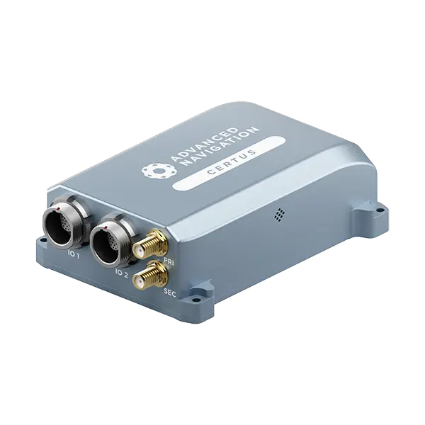
Market-leading dual antenna INS
Roll & Pitch
0.1 °
Heading (GNSS)
0.1 °
Bias Instability
3 °/hr
Position Accuracy
10 mm
View Solution
Ultra-high accuracy MEMS INS
Roll & Pitch
0.03 °
Heading (GNSS)
0.05 °
Bias Instability
0.2 °/hr
Position Accuracy
10 mm
View Solution
The Latest News, Articles & More

Europe Expansion with High-Profile Military Appointment
16 June 2026
Go to ArticleHow Improved Positional Accuracy Can Transform Mining Excavation
15 June 2026
Go to Article
High-Precision Navigation at Scale for Counter Drone Technology
18 May 2026
Go to Article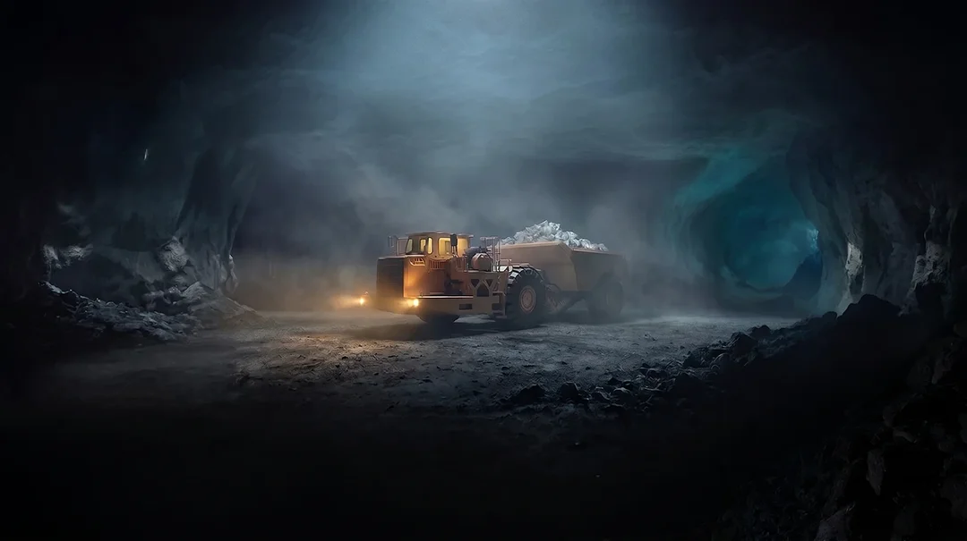
Navigating the Future of Mining Operations
5 May 2026
Go to Article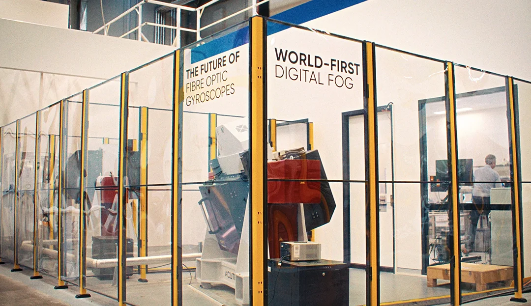
How Advanced Navigation’s Manufacturing Ensures Consistent Product Quality
27 April 2026
Go to Article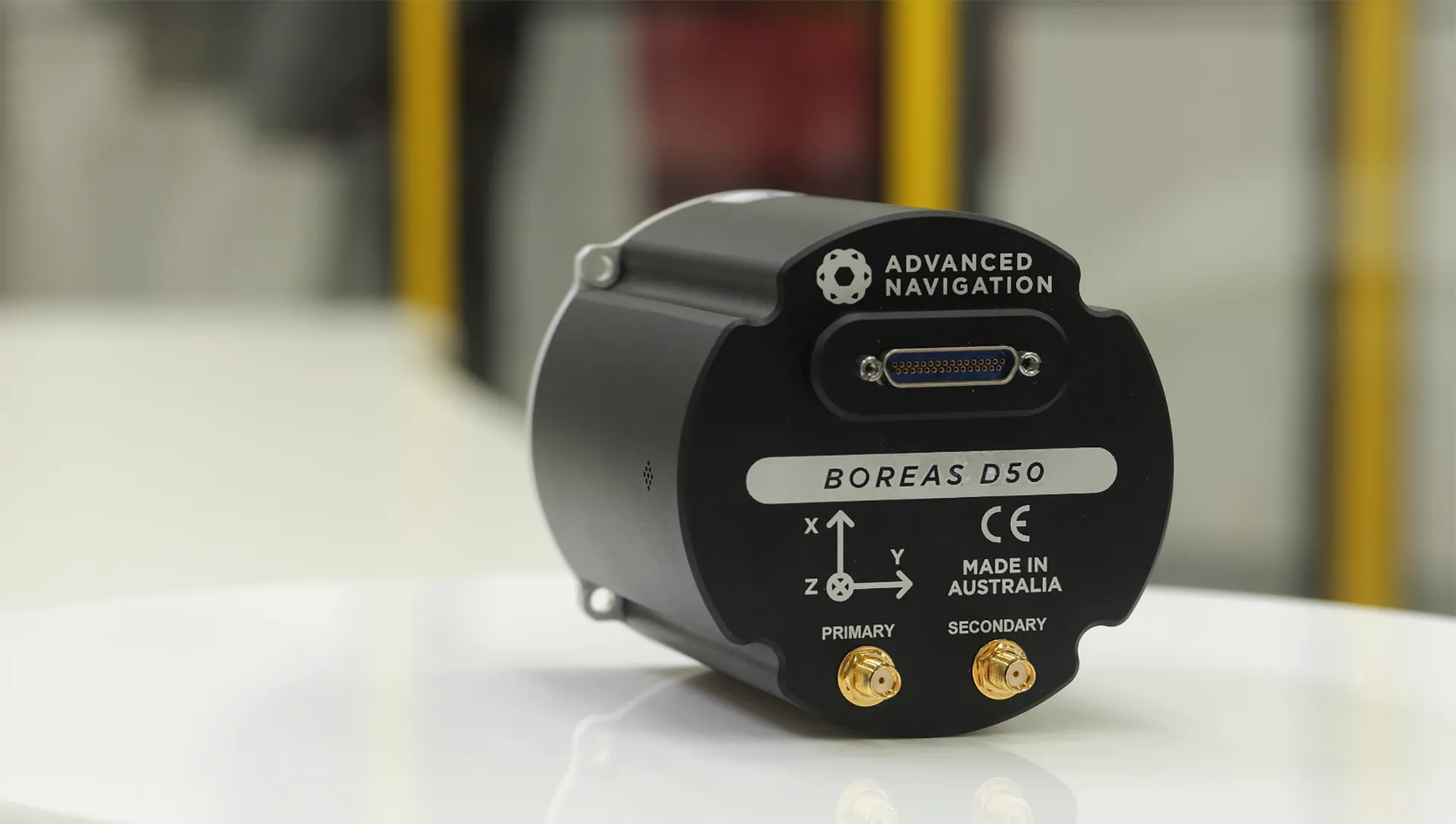
How a Compact North Seeking Gyro Delivers Precision Underground
16 April 2026
Go to ArticleCommon Questions about MEMS GNSS/INS
What is a MEMS GNSS/INS?
MEMS (Micro-Electro-Mechanical Systems) can be defined as a super-miniaturized component that combines mechanical and electrical elements into a form factor that can range in size from a few milimeters down to micrometers.
MEMS components can vary in complexity ranging from no moving elements to complex electromechanical systems with integrated microelectronics.
Examples of MEMS components used in navigation applications include accelerometers, gyroscopes, magnetometers and pressure sensors. A MEMS-based INS is a position, velocity and orientation sensor that uses a MEMS-based accelerometer, gyroscope, magnetometer and pressure sensor as its core sensing components.
Why should you use a MEMS GNSS/INS?
Compared to other INS solutions, a MEMS INS has a lower size, weight, power consumption and cost (SWaP-C). There are several benefits to using a MEMS INS:
- Reduced cost: A MEMS INS is not as costly as a FOG-based (fibre optic gyroscope) INS
- Lightweight and small: By nature, MEMS are built on a miniature scale and measure in micrometers. This makes a MEMS-based INS an ideal fit for vehicles or machines that need a small payload.
- Flexible placement: The more compact nature of MEMS technology also allows the INS to be mounted in variable positions
- A wide range of applications: While FOG INS has been proven to be incredibly effective, improvements to the accuracy of MEMS technology for inertial navigation solutions have proven to be more cost-effective for applications such as precision agriculture and autonomous vehicles
- GNSS integration: With any kind of inertial navigation system, a MEMS INS isn’t able to determine absolute position. By itself, the MEMS INS is able to determine the relative position of the vehicle from a known starting point, accounting for distance travelled and orientation. When a MEMS INS is combined with GNSS (global navigation satellite system) it takes advantage of the satellite technology to accurately determine the absolute position on Earth. With these two navigational technologies working in tandem, the strengths of both enable a high level of accuracy.
- Low power consumption: MEMS technology has advanced to the point where it can reduce power used, utilizing power cycling and low power modes
Given the low SWaP-C of MEMS INS, it has a wide range of applications, from commercial-grade to survey-grade and defence-grade. This includes:
- Smartphones
- Precision agriculture
- LiDAR
- Radar
- Aerial surveying
- Marine surveying
- Space exploration
- Ultrasonic sensors
- Cameras
- Wearable technology
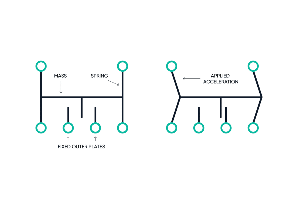
How does a MEMS accelerometer work?
A MEMS accelerometer senses the forces of acceleration acting on a vehicle or device. A common array uses an outer assembly with a series of fixed plates with a movable assembly located internally.
This internal assembly has a small mass and is connected to the outer assembly with spring contacts. It also has internal plates that form multiple capacitors. As force is implemented the internal assembly moves, and this displacement changes the capacitance value, which is measured to determine the acceleration that has been applied.
How does a MEMS gyroscope work?
A MEMS gyroscope measures the rate of rotation. Unlike an accelerometer, a gyroscope uses a two-mass system that moves in opposite directions continuously, experiencing equal velocity.
When the vehicle or device has angular rotation applied the MEMS gyroscope will begin to measure the difference in velocity, also known as the Coriolis Force.
How does a MEMS magnetometer work?
A MEMS magnetometer is used to detect and measure magnetic fields. One sensing method used by MEMs magnetometers is special resistors that have a strong magnetic field applied during manufacture to orient their magnetic domains in the same direction.
During operation, any external magnetic field applied to the resistor causes the magnetization to rotate and change the angle. This can be measured as a variation in the resistance. will begin to measure the difference in velocity, also known as the Coriolis Force.
How does a MEMS pressure sensor work?
MEMS pressure sensors typically use piezoresistive pressure sensors. The piezoresistive sensor measures changes in the electrical resistance when pressure is applied.
How does a MEMS sensor work for inertial navigation?
A MEMS GNSS/INS calculates changes in an object’s position and movement. This is achieved through the functions of inertial sensors like three-axis gyroscopes and accelerometers that measure changes in orientation, rotation, and velocity.
How do inertial sensors work in MEMS GNSS/INS?
As the object moves, MEMS sensors pick up on these changes to accurately measure how it moves and the speed at which it travels. This can be combined with data from a GNSS (Global Navigation Satellite System) to accurately determine a vehicle’s location. The satellite data from the GNSS will feed more information into the central unit, providing additional information on the travel of the object and providing more insights as to what the inertial measurement unit (IMU) is measuring.
What applications are typically suited for MEMS-based INS?
MEMS-based INS are suitable for most applications, including but not limited to:
- Marine Surveying
- Land Surveying
- UGVs
- Helicopters
- Antenna Targeting
- Surveying
- Robotics
- UAVs
- Marine
Some other requirements to consider when deciding if a MEMS-based INS is a suitable solution include:
- What navigation accuracy is required?
- What size, weight and power consumption (SWaP) requirements do you have?
- How much are you willing to pay? Note that MEMS-based INS are considerably cheaper than FOG or RLG-based INS.
Our INS suit most applications and include a free trial offer.
What are the advantages of MEMS GNSS/INS?
While MEMS technology cannot compete with fibre-optic gyroscope (FOG) or ring laser gyroscope (RLG) in terms of performance, a MEMS-based INS offers:
- Smaller size and weight – MEMS components range in size from a few milimeters down to micrometers, making the overall INS package very small and ideal for payload-sensitive applications.
- Less power consumption – MEMS sensors consume less power than their FOG/RLG counterparts. This makes them ideal candidates for applications using batteries.
- Lower cost – MEMS components are assembled onto circuit boards in a similar manner to semiconductor devices. This manufacturing process allows for MEMS-based INS units to be mass-produced easily in a cost-effective manner.
What is the Difference Between GPS and GNSS INS?
GNSS (Global Navigation Satellite System) is a term to describe all satellite constellation systems that transmit satellite position and timing data to a GNSS receiver to calculate the receiver’s position, velocity and time. GPS (Global Positioning System) is a North American-run GNSS constellation system, one of the six GNSS constellations used worldwide. The GPS constellation is the oldest, most established GNSS constellation. The term GNSS and GPS are often interchangeably used even though they are not the same. A good analogy to this confusion would be how people interchangeably use the term iPhone to describe smartphones. An iPhone is a type of smartphone, but a smartphone is not necessarily an iPhone. GNSS receivers these days can receive satellite signals from multiple constellations (Not just GPS constellations) to improve their positioning capabilities.
A GNSS-aided INS system is commonly referred to as GNSS INS or simply INS. A GNSS INS fuses data from the following sensors:
- IMU
- GNSS (Internal or external to the INS sensor package)
- Optionally Magnetometer
- Optionally other external aiding systems
The fused navigation output data of a GNSS INS helps produce a more accurate, reliable and importantly usable navigation result compared to a stand-alone AHRS (INS system without a GNSS receiver ) or GNSS system.
For more details on how an INS works, see the INS FAQ.