Global Navigation Satellite System (GNSS) and Satellite Navigation Explained
Share:
Published on:
Table of Contents
- What is Global Navigation Satellite System (GNSS)?
- The Primary Uses for Global Satellite Navigation System (GNSS)
- How Global Satellite Navigation System (GNSS) is Used to Attain Absolute Position
What is Global Navigation Satellite System (GNSS)?
GNSS stands for global navigation satellite system. A Global Navigation Satellite System (GNSS) consists of a constellation of satellites orbiting the Earth in very specific trajectories. For global coverage, it is estimated that a constellation requires 18 to 30 satellites. Navigation satellites provide orbit information and accurate timing (and other services) to radio receivers specifically designed to receive those satellite signals and decode the signal message contents. With the contents of the messages from at least four “visible” satellites, the position on or near most of the Earth’s surface can be calculated using a mathematical process known as trilateration.
GNSS is often generically referred to as GPS (Global Positioning System) but that acronym actually refers specifically to the United States constellation. There are several GNSS constellations provided by governments around the world, including:
In addition, there are some other systems that are engineered to service specific regions only, rather than offering a global service. These are known as RNSS (regional navigation satellite systems) including:
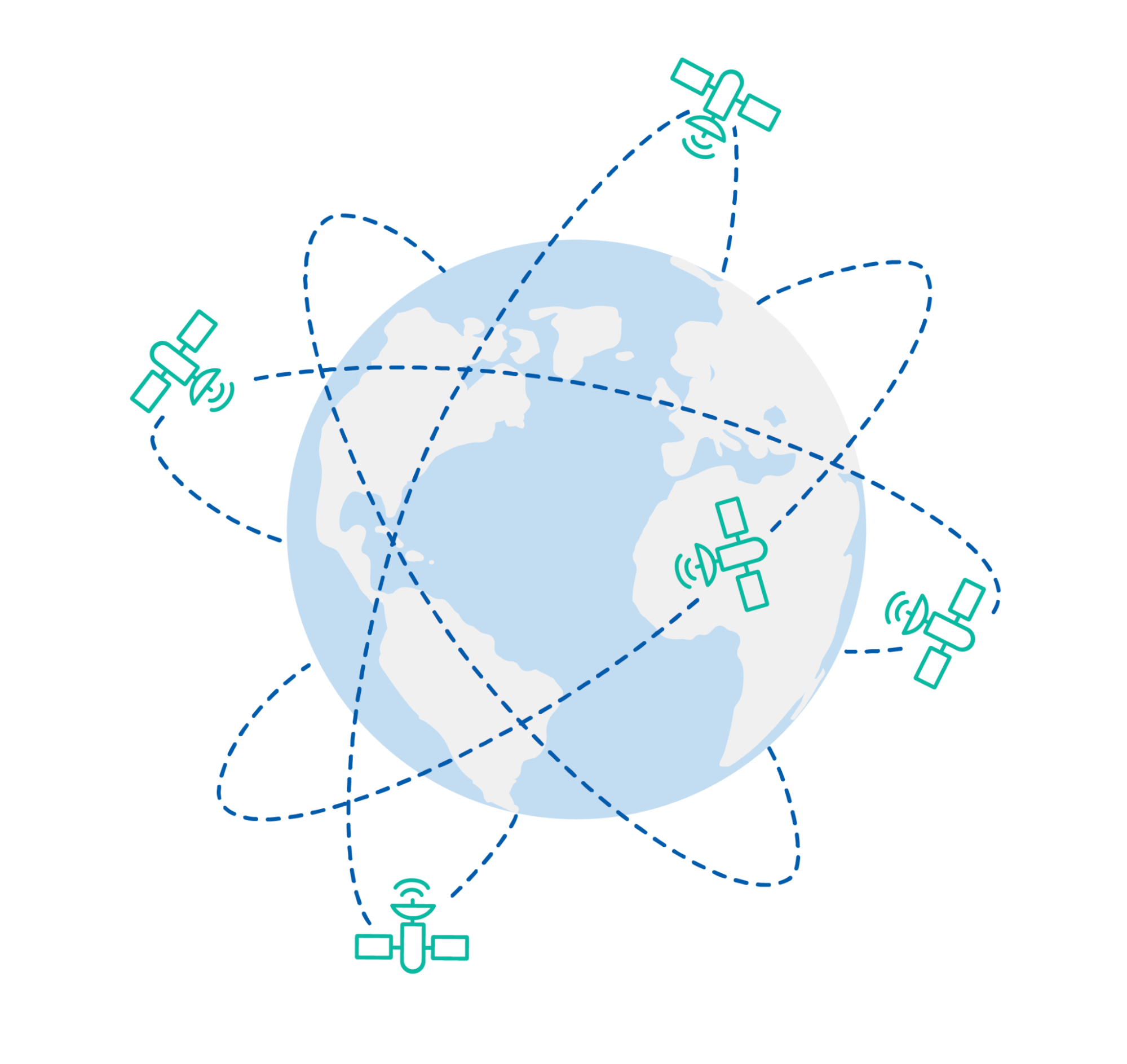
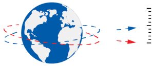
There are several GNSS satellite constellations orbiting the Earth. Each providing data for positioning in various continental areas
Today, most GNSS receivers can receive and decode signals simultaneously from more than just a single satellite constellation. This means that they can be used globally for immediate deployment and can provide wider use than receivers that are limited to a single GNSS constellation.
History of Global Positioning System (GPS)
The United States global positioning system (GPS), originally termed “Navstar GPS”, was the first operational satellite navigation system. Global positioning system (GPS) development commenced in the early 70s, with the first satellite launched in 1978. The original use was intended for military purposes as a location and positioning system, followed later by GPS being [partially] opened up to civilian and commercial use.
A full 24-satellite constellation that offered global coverage became operational in 1993. Since this time, the use of GPS and other GNSS constellations has become synonymous with a vast array of commercial, defense and civilian applications and services that continue to shape many aspects of our lives.
The Primary Uses for Global Satellite Navigation System (GNSS)
There are two primary uses for GNSS:
- Position determination
- Timing
Position of an object is its latitude (distance from the equator), longitude (distance from the Greenwich meridian in the UK) and elevation above (or below) mean sea level. This is known as “absolute position”. The absolute position of a GNSS receiver can be determined when the signal from four (or more) GNSS satellites can be clearly received at the same time. In dynamic applications, such as moving vehicles, when the position of the GNSS receiver is known over a period of time as the vehicle moves, tracking and navigation applications become possible.
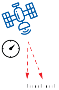
The signals, sent over radio waves, from GNSS satellites have extremely accurate time stamps (and other information) encoded into them. This is enabled by the use of incredibly accurate (and very high cost) atomic clocks on board each satellite. Once the GNSS receiver has determined its position (and this is a requirement), the GNSS receiver synchronizes its internal (much less accurate) clock with the satellite clocks. By maintaining that synchronization, the GNSS receiver clock is then considered to have a very accurate timing source. Many industries now rely heavily on these highly accurate GNSS receiver-based clocks including banks, stock exchanges, telecommunications companies and electricity suppliers.
How Global Satellite Navigation System (GNSS) is Used to Attain Absolute Position
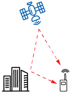
Using GNSS constellations to determine position is based on the principle of trilateration. Trilateration differs from triangulation in that it uses the direct measurement of distance from multiple points to determine a location, whereas triangulation measures the angles from fixed points that converge to determine a location. A GNSS receiver uses trilateration to calculate its location on Earth, based on the distance of the receiver from multiple satellites.
The Basics of GNSS Trilateration
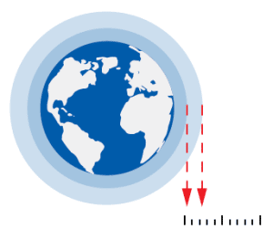
The signal from a single satellite provides a general location of a point around the perimeter of a circular area that covers approximately 35% of the Earth’s surface – a huge area. Note that the location is not within the area of coverage, but on the perimeter because the distance to the satellite is a known length and anywhere inside of the perimeter will be a different, shorter distance. When a second satellite can be seen, the coverage of that satellite will overlap part of the first satellite coverage. This means that the GNSS receiver is at one of the two points of intersection of the perimeters of the coverage areas. When a third satellite can be seen, the point of intersection of all three coverage area perimeters will be the location of the GNSS receiver. That is, an accurate two-dimensional (longitude – X and latitude – Y coordinates) position of the GNSS receiver on the Earth’s surface.
When a fourth satellite can be seen, elevation or altitude can be determined with trigonometry using the X-Y coordinate and the additional “line” to the fourth satellite (it could be said, the shorter this distance, the higher the elevation).
The GNSS receiver now has a three-dimensional position fix; that is, X-Y coordinates plus altitude/elevation (Z). The more satellites that can be seen, the easier it is to resolve position with enhanced precision.
Image depicting how trilateration works. The location of the GNSS receiver is somewhere on the perimeter of the first satellite coverage area. When a second satellite can be seen, the location must be at one of the two points where the perimeters intersect. When a third satellite is visible, the intersection of all three coverage perimeters is the two-dimensional location and the remaining point of intersection is ignored. A fourth visible satellite enables elevation/altitude to be calculated.
The GNSS receiver can perform trilateration and provide accurate position only if it knows:
- Where the satellite is,
- Exactly when the signal was sent from the satellite, and
- Exactly what time the signal is received
The first two requirements are easily understood as information on the satellite location in its orbit and the time the signal was sent are contained within the signal that the satellite sends.
The third requirement is more complicated because the GNSS receiver has a relatively low accuracy clock inside it. This is due to size, weight, power consumption and cost constraints in GNSS receivers – it is not feasible to equip a GNSS receiver with an atomic clock like those used in the GNSS satellites. The low cost receiver clock is simply not accurate enough when measuring the time of arrival of signals traveling at the speed of light – a clock timing error of just one thousandth of a second equates to a 300 km position error.
Clearly, a method of resolving the issue of receiver clock accuracy is required. Fortunately, basic algebraic principles come into play: we can say that we have four unknowns to solve when calculating a position: latitude, longitude, elevation, and receiver clock error. This could be written like this:
Position = latitude + longitude + elevation + clock error
It is not necessary to delve further into this mathematically, but suffice it to say that if we have measurements of four (or more) different satellites simultaneously, we can solve our position equation with the four unknowns.
Satellites and Orbits
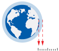
GNSS satellites are placed in a medium Earth orbit (MEO) of around 20,000 km which means they circle the earth approximately every 12 hours. As it is necessary to see at least four different satellites at all times to obtain a position, it has been calculated that a minimum of 24 satellites are required in a constellation to provide a 24/7 global service.
The individual satellites are grouped into orbital planes that typically optimize visibility in populated areas. This means, for example, that the Arctic and Antarctic regions are not guaranteed to always have the minimum four satellites visible.
Some GNSS constellations have more than 24 operational satellites in orbit. The United States GPS system currently has 35. Some of the additional satellites are designated as spares for redundancy purposes, and some are used to supplement specific orbital planes to improve service reliability and accuracy.
Frequencies and Signals
The signals sent from the satellites in space to the GNSS receivers are complex and vary in structure and frequency. Different frequencies are used to improve signal reliability, signal accuracy, and system redundancy. For example, some signal frequencies are better suited to pass through trees due to the different signal wavelengths. In addition, by using multiple frequencies simultaneously, modern multi-frequency GNSS receivers can improve the position accuracy by measuring the difference in signal propagation through the atmosphere, and effectively remove it as a source of error. Some GNSS frequency examples are listed below:
- GPS: L1 – 1575.42 MHz, L2 – 1227.60 MHz and L5 – 1176.45 MHz
- GLONASS: L1 – 1602.0 MHz, L2 – 1246.0 MHz and L3 – 1202.025 MHz
- Galileo: E1 – 1575.42 MHz, E5a – 1176.45 MHz, E5b – 1207.14 MHz and E6 – 1278.75 MHz
- BeiDou: E1 – 1575.42 MHz, E2 – 1561.098 MHz, E5B – 1207.14 MHz and E6 – 1268.52 MHz
In addition to the varying (and sometimes overlapping) frequencies used by the different GNSS constellations, the signal information is modulated onto the carrier frequency in many different ways. It is beyond the scope of this article to detail the mathematics behind the various modulation methods and for a general user it is unnecessary to know, but as an example, the Galileo system uses these methods in their signals:
- E1-I CBOC (6,1,1/11)
- E1-Q BOCcos (15,2.5)
- E5a AltBOC (15,10)
- E5b AltBOC (15.10)
- E6-I BPSK (5)
- E6-Q BOCcos (10,5)
The different modulation methods are designed to maximize the signal-to-noise ratio during de-modulation, whilst simultaneously avoiding interference from other signals from their own, and other GNSS satellites.
Lastly, it should be noted that some of the signals broadcast by the GNSS satellites are deliberately encrypted to ensure their use is restricted. The most common use-case for these signals is the high-accuracy signals used by the military.
Improving Accuracy and Precision
Typically speaking, using GNSS and commercial grade GNSS receivers alone provides position accuracy within a radius of ~2 to 5 m. In non-critical applications, such as vehicle navigation systems and phone location, being within 5 m is likely okay. For applications that require very high levels of accuracy, such as surveying and geospatial applications, position accuracy of ~10 mm may be expected.
In navigation, accuracy and precision, although seemingly similar, are not the same thing. Accuracy is purely how close to absolute position the navigation system is estimating itself to be. Precision, on the other hand, is more to do with how repeatable or how consistent the system is. Ideally, the GNSS receiver provides both accuracy and precision.
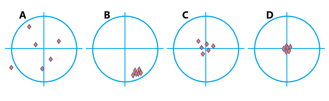
Image depicting accuracy and precision – (A) is neither accurate nor precise; (B) is precise but not accurate; (C) is accurate but not precise; (D) is both precise and accurate
Global Navigation Satellite System (GNSS) Limitations and Sources of Error
There are a number of factors that limit (or potentially limit) the use of GNSS. The primary factor is the imperfect reception of the signal as received by the GNSS receiver from the individual satellites. Malicious radio interference, known as spoofing or jamming, of GNSS to corrupt the signal so that it cannot be received coherently happens – this requires a strategic approach to overcome that is outside the scope of this article.
Outside of jamming and spoofing, or otherwise by accident, there are several phenomenon that can introduce imperfect signal reception:
Error Type: Ionospheric
Range: ± 5 m
Signal propagation delay – upper atmosphere is loaded with electrons caused by ionizing solar radiation that can “bend” and reflect radio waves.
Error Type: Orbit
Range: ± 2.5 m
Position drift – as with clocks, minuscule errors in satellite orbit position become much larger when used for position calculation on Earth.
Error Type: Clock
Range: ± 2 m
Timing drift – due to the distances, tiny timing errors in satellite clock accuracy become much larger errors on Earth.
Error Type: Multipath
Range: ± 1 m
Signal replication due to reflection off objects such as buildings and terrain.
Error Type: Tropospheric
Range: ± 0.5 m
Signal propagation delay – lower atmosphere is far denser than other atmospheric layers and can refract radio waves.
Error Type: Receiver noise
Range: ± 0.3 m
GNSS receiver hardware and software induced signal noise that affects accuracy of perceived signal.
The above sources of error can be broadly categorized as effects that delay the signal, and thus cause issues with the timing of the signal reception. For example, when receiving a reflected signal and not the original line-of-sight signal, which is common in dense urban areas due to tall buildings that create “urban canyons”. Of course, a complete blockage of the signal, such as when in a tunnel, underground or underwater results in a complete loss of all satellite signals.
Highly sophisticated, modern GNSS receivers can deftly handle some of these issues using elegant mathematical techniques to determine the types of errors being encountered and applying offsets or corrections as required. Some of these capabilities are making their way into the lower cost, commodity GNSS receivers, such as those found in mobile phones. Despite having the capacity to correct some signal reception errors, when there is a complete loss of all satellite signals, the only real solution is to incorporate an inertial navigation system (INS) to estimate position calculations whilst inside the tunnel. This is known as dead-reckoning.
GNSS Base Stations and Error Correction Solutions
Several ways of improving GNSS accuracy have been implemented outside of improving the performance of GNSS receivers. The primary means is through the installation of ground base stations that serve as on-Earth references for GNSS. The goal of base stations and GNSS error correction services is to establish the true path of the GNSS receiver, or as close to its true path as possible, in relation to an absolute position on the Earth’s surface.
The base station receives GNSS signals and uses sophisticated measurement techniques to precisely calculate distances to observable satellites and thus to calculate GNSS signal errors; for example, ionospheric delay. All measurement and error correction data made at each base station is logged and archived. This data is used for various error correction solutions, some of which are outlined below:
- Real-time kinematics (RTK) – GNSS receivers use data broadcast from fixed base stations to eliminate a range of errors. The errors are eliminated by differencing measurements from the GNSS receiver to two or more satellites and from the base station to the same satellites. RTK may involve higher initial cost and licensing for correction services, however, can provide ~10 mm accuracy.
- Satellite-based augmentation system (SBAS) – A network of ground reference stations that provide satellite clock, ephemeris and signal propagation corrections via geostationary satellites, based on satellite observation from multiple reference locations.
- Precise Point Positioning (PPP) – A network of ground reference stations equipped with high-precision GNSS receivers and antennas that continuously track GNSS signals and broadcasts. Processed satellite orbit and clock data is then broadcast to PPP users to provide accuracy to ~10 mm.
- Post-processing kinematics (PPK) – Software or online services that process uncorrected (“raw””) navigational data to achieve equivalent or even better than RTK accuracy. Importantly, PPK is suited to applications that do not require real-time corrections; for example, UAV surveying missions. To learn more about PPK correction solutions, read our “Benefits of using post-processing kinematic (PPK) software” article.
More on SBAS and PPP
Satellite-based augmentation systems (SBAS) and precise point positioning (PPP) are technologies that improve the accuracy, integrity, and reliability of global navigation satellite system (GNSS) signals. The main objective of SBAS and PPP is to provide an accurate and reliable positioning solution that can be used in various applications such as aviation, maritime, land surveying, and location-based services.
SBAS
SBAS is a technology that uses a network of ground reference stations, satellite links, and processing facilities to determine GNSS errors caused by various atmospheric and environmental factors. The calculated errors are then broadcast to users via a geostationary satellite, allowing users to apply the necessary GNSS correction factors and improve system accuracy. SBAS’s are designed to provide a range of services, including accuracy, integrity, availability, and continuity, to meet the needs of various applications, predominantly aircraft. SBAS also provides warnings to users if GNSS signals are not reliable. This is particularly important in safety-critical applications such as aviation and maritime.
The most widely used SBAS systems are the “wide area augmentation system” (WAAS) in the United States, the “European geostationary navigation overlay service” (EGNOS) in Europe, and the “multi-functional satellite augmentation system” (MSAS) in Japan. The main limitation of SBAS is that the individual systems only cover specific areas and global coverage is not available.
PPP
PPP is a technique that can achieve centimeter-level accuracy without the need for a local reference station or real-time corrections. It uses a network of ground-based reference stations equipped with high-precision GNSS receivers and antennas that continuously track the signals from the GNSS satellites. The data collected by these reference stations is then processed using a technique known as “integer ambiguity resolution” to determine the precise orbit and clock information for each satellite.
Once precise orbit and clock information has been calculated, it is broadcast to PPP users via various means, such as the internet or satellite links. Requiring this additional communications channel is the main limitation of using PPP.
PPP is particularly useful in applications where a local reference station is not available or practical, such as surveying, precision agriculture, and geodesy. PPP can also be used in conjunction with SBAS to further improve the accuracy of GNSS signals.
PPP and SBAS Integration
PPP and SBAS can be used together to provide high-accuracy positioning solutions. PPP can provide a baseline solution that is then refined using SBAS correction information. This is known as PPP-RTK, or Real-Time Kinematic, which combines the high accuracy of PPP with the real-time correction information provided by SBAS. PPP-RTK is particularly useful in applications where high-accuracy positioning is required in real-time but a local reference station is not available or practical, making it suitable for applications such as precision agriculture, construction, and machine control.
Recent Tech Articles
How Improved Positional Accuracy Can Transform Mining Excavation
Explore the new standard in absolute positioning for GNSS-denied environments. See how the Chimera Land LVS and INS pairing anchors real machine motion.
15 June 2026
Go to Article
High-Precision Navigation at Scale for Counter Drone Technology
Unlock precision for your kinetic effector on-the-move. Discover how Advanced Navigation delivers the stabilization and supply chain speed needed for scalable counter drone defense.
18 May 2026
Go to Article
Navigating the Future of Mining Operations
Discover how to improve product quality in manufacturing through Advanced Navigation's rigorous supply chain and exhaustive validation.
5 May 2026
Go to Article