The History of Gyroscopes – From Humble Beginnings to Hyper Technology
Share:
Published on:
Table of Contents
- Gyroscope Beginnings
- Basics of Gyroscope Sensor Technology
- The First Practical Use of Gyroscopes in Navigation – The Gyrocompass
- Current Gyroscope Sensor Technology
Gyroscope Beginnings
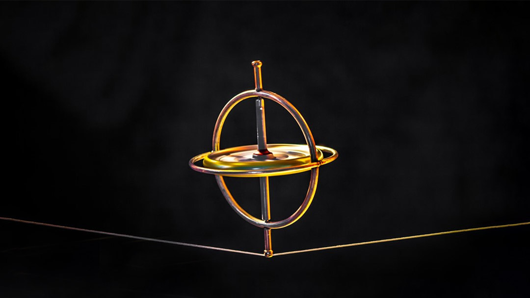
The gyroscope most likely began existence as a simple children’s toy – a “spinning top”. Perhaps poking a stick into the bottom of an orange and spinning it was the first spinning top – while spinning fast enough, the fruit remains balanced on the stick until it slows down, begins wobbling, before finally toppling over. Magic! It is difficult to speculate who, when and where first discovered this seemingly gravity defying wonder, however, it has endured the ages and has ended up becoming an intrinsic part of human navigation.
The magic of how a spinning object enables it to balance on a point has widened the eyes of youngsters the world over (at least until the dawning of the television and digital age) and became of deep intrigue to more mature thinkers trying to understand how this miraculous, impossible balance can possibly happen. It is quite possible that how a spinning top remains upright and balanced—even when placed on an inclined surface—began the idea of what was to later become the gyroscope.
Basics of Gyroscope Sensor Technology
Using a flat disc with a pin through the centre of it as the spinning top made the balancing phenomenon more observable. Increasing the mass of the disc, especially when the majority of its weight is toward the outside of the disc, and increasing the spin rate, extended the duration of the spin induced balance. The faster the disc spins or the larger its moment of inertia, the greater its angular momentum will be.
The method developed to enable more careful observation was to capture the spinning disc within a mechanical frame so it could be manipulated without touching the disc. To do this, each end of the spinning top axle is connected to the frame using bearings or some other means to minimize friction between the axle and frame. Spinning up the disc in the frame, followed by holding the frame at different angles, resulted in a fascinating phenomenon where the rotating disc resisted its repositioning. Unbeknownst to the first observers, this “invisible hand” is actually the effect of what is called gyroscopic precession.
Gyroscopic Precession
Gyroscopic precession is the reaction that a spinning object has to its axis of rotation being tilted. The spinning object responds to tilting with a torque that is perpendicular to both the external influence and its axis of rotation, according to the right-hand rule. While this might be difficult to visualize for a disc within a frame, a more intuitive example is the behavior of an unbalanced spinning top. Rather than falling over or righting itself, either of which would break the law of conservation of angular momentum, the unbalanced top will move in a circular pattern. More specifically, as a consequence of gyroscopic precession, the reactive torque acts about an axis that is 90 ° to the torque applied by gravity, resulting in a circular motion. Gyroscopic precession is essentially how, when an external torque force is applied to a spinning object to tilt its axis of rotation that would otherwise tilt its axis of rotation, the reaction does not directly resist this torque force, as one might expect. Instead, this resistive torque occurs at 90 º to what intuition might result in a torque which affects the axis of rotation of the disc at 90 ° to the direction that the force is applied. Further detail on gyroscopic precession is outside the scope of this article.
Harnessing the Gyroscope Using a Gimbal
Curious minds decided that mounting the spinning disc in a gimbal would allow them to further explore this sensation. A gimbal (the origins of the gimbal indicate that it was invented several centuries BC) is a supporting frame assembly that allows independent movement between the gimbal frames and the object attached to it. In this instance, the inner gimbal frame, which holds the spinning disc axle, is connected to the outer gimbal frame at 90 ° (orthogonally). Each point of attachment between each component is pivoted in a way to minimize friction between the parts that otherwise affects gyroscopic effects. The outer gimbal is attached at the top and bottom using pivots to a frame that can be mounted. This results in an assembly that we might refer to as the classical mechanical gyroscope, with the gimbals able to rotate around the X, Y and Z-axis.
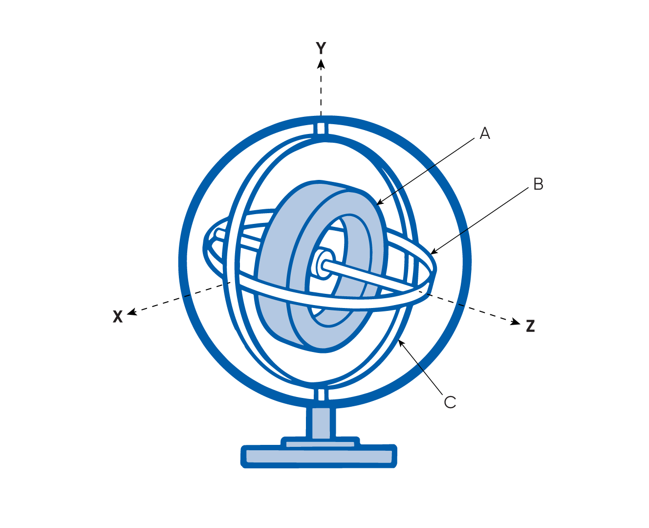
Image depicting a classical mechanical gyroscope design. The spinning disc (A) is mounted to the inner gimbal (B), which is mounted at 90 ° to the outer gimbal (C). The outer gimbal is able to rotate with respect to the mounting frame. This arrangement provides independent rotation of the gimbals, allowing the spinning disc to retain its original axis of rotation regardless of the orientation of the gyroscope
Gyroscopic Motion
Gyroscopic motion refers to the inherent inclination of a spinning object to preserve its rotational alignment. When an object rotates, it acquires angular momentum, which must be conserved. Consequently, the object opposes any alteration to its axis of rotation since such changes would cause a modification in its angular momentum.
Conservation of Angular-Momentum
With the gimbal arrangement, it could be seen that the axis of rotation of the spinning disc remains in the same orientation even when the gyroscope is rotated or tilted in 3D space. This is the conservation of angular momentum of the spinning disc and the resulting forces generated when the orientation of the gyroscope changes. Changes in orientation of the gyroscope cause the positions of the gimbals to alter so the spinning disc retains its original axis of rotation. Note that the faster the disc is spinning, the greater its angular momentum and resistance to changing orientation. The reaction to changed orientation likely led to the idea of being able to gauge orientation with reference to the spinning disc.
The First Practical Use of Gyroscopes in Navigation – The Gyrocompass
The advent of the electric motor made practical, long-term use of gyroscopes possible by being able to keep the disc spinning at constantly high speed. In a navigational sense, if gyroscopic effects could be harnessed and controlled with relation to North, based on the Earth’s axis of rotation, then a gyro could be part of a non-magnetic based navigation system.
For modern mariners aboard steel-hulled vessels, a non-magnetic heading source that relates to true / geographical North, would greatly improve navigational accuracy. Not only that, but it could remove the complexities of traditional celestial navigation, or the errors associated with magnetic compasses in the presence of ferrous metals (steel, iron etc). Note also the fact that magnetic North is almost always different to true North. To this end, Hermann Anschütz-Kaempfe developed a functional “gyrocompass” in the early 20th century.
The Anschütz gyrocompass enabled changes in the direction (heading) of the vessel to be observed without using a magnetic compass. Gyrocompassing, as it became known as, can be attained in several ways; for example, surrounding the gimbal with a degree graduated ring enables rotation of the gimbal to point to the new direction (much like a magnetic compass needle). Another means is to trap the gimbal and measure the torque generated by the gyroscope when its direction changes, in order to calculate the rotational movement.
A Quick Look at Inertial Navigation Systems (INS)
The emergence of the autonomy revolution and the ability for us to build vehicles, machines and systems that operate without human control or intervention requires very high levels of reliability in terms of navigation, control, and safety. A primary component of such systems is a navigation system; typically an inertial navigation system (INS).
A typical INS is able to provide various navigational and orientation data for a vehicle. That is, roll, pitch, and heading of the device / vehicle. This data is provided by sensors that can detect changes in linear acceleration in each axis and, of course, gyroscopes for detecting rotation around each axis. Heading may be provided by magnetometer type sensors or a fibre-optic gyroscope, for example. Absolute position or location data for where the vehicle / device is in the world is usually obtained using GNSS. In instances or applications where GNSS is unavailable as a reference for location, the INS can step in to provide navigational data based on estimating changes in motion, which is referred to as dead-reckoning.
Current Gyroscope Sensor Technology
The modern era of electronics, computing, photonics, and greatly improved manufacturing has indelibly affected the gyroscope. The concept of the gyroscope remains unchanged, however, the technology behind how we build and use gyroscopes has evolved and changed significantly over the last 100 years. Our desire to develop and adopt new technologies that provide superior accuracy, smaller size, lower weight and reduced cost is a driver of technological innovation that spans the gamut of commercial, industrial, and defense oriented applications.
The above may be coupled with our increasingly insatiable appetite for gathering and analyzing data. Sensing capabilities are continuously evolving that enable high resolution data capture at previously unimagined levels. These activities require accurate navigation systems that contain equally accurate gyroscopes. Furthermore, the age of space and subsea exploration, satellites, robotics, miniaturization, and unmanned vehicles are creating new opportunities and industries seeking to reduce costs, remove inefficiencies, limit resource usage, and cut greenhouse gas emissions. It is fairly safe to say that all of the above mentioned systems require gyroscopes in some way and these, by definition, need to follow suit in many ways.
MEMS Gyroscopes
MEMS (micro-electromechanical systems) is a process technology that emerged from integrated circuit (IC) manufacturing in the 1960s that combines electrical and mechanical elements in extremely miniaturized, chip-state form factors. MEMS devices are excellent for large-scale production and are, therefore, relatively inexpensive to produce. MEMS gyroscopic sensors are commonly found in commercial, industrial, up to tactical grade inertial navigation systems. Even a typical smartphone will contain MEMS gyroscopes that are used for detecting phone orientation (portrait or landscape display) and in navigation applications, for example. A MEMS gyroscope is a component that is a combination of electrical and mechanical elements that indicate acceleration about a single or multiple axes.
The most common MEMS gyro technology uses the Coriolis effect. The Coriolis effect is the apparent deflection caused to a moving object caused by the Earth’s rotation and latitude. To illustrate, when a plane takes off at the equator and flies due North, as the plane flies, the Earth is rotating. The result is the plane travels in a left curving arc relative to the Earth’s surface, although it has travelled straight. At higher latitudes, the Coriolis effect becomes more prevalent due to the reducing circumference of the Earth.
In a typical Coriolis effect MEMS gyroscope, a proof mass is suspended in a frame using springs. The proof mass is made to oscillate at a specific resonance – this is the drive axis. This frame is located in a second frame, with springs that are set at 90 ° to the drive axis that isolates the two frames. The sprung motion of the second frame is the sense axis. When the gyroscope is rotated, the Coriolis effect induces a secondary vibration along the sense axis (perpendicular to the drive axis), that shifts the proof mass and inner frame against the direction of rotation, producing a change in capacitance that is proportional to the Coriolis force / sensed rotation.
Image depicts the operation of a simple MEMS Coriolis effect gyroscope. The springs (A) hold the proof mass (B) in position within the inner frame (C), creating the drive axis. The inner frame is isolated from the outer frame (D) using springs (E) set at 90 ° to the drive axis, creating the sense axis. The inner frame has several protruding fingers (i). The fixed electrodes (ii) make up differential capacitors, with a protruding finger from the inner frame between the capacitor electrodes. During rotation, the Coriolis effect causes movement of the proof mass / inner frame against the direction of rotation that results in a change in capacitance that is proportional to the rate of rotation
Note that MEMS Coriolis effect gyroscopes provide rotation information within the inertial reference frame of the device only. This means they cannot provide heading information, just rotation information of the device. A secondary means of attaining heading is required; for example, using magnetometers.
Fibre-Optic Gyroscopes
The fibre-optic gyroscope (FOG) is a photonics / laser based gyro technology that was first demonstrated in the mid 1970s. FOGs are renowned for very high accuracy and resistance to drift that makes them well suited to high-end tactical, navigation and strategic applications. A typical 3-axis FOG based INS has three coils of optical fibre for the X, Y and Z axes that are placed orthogonally (at 90 °) to one another, a laser emitter or similar narrow bandwidth light source, and an optical receiver.
The basic operating principle of a typical fibre-optic gyroscope is that the laser emits light that hits a semi-reflective mirror, which splits the beam into two. The two light beams then enter the coil winding at either end and travel simultaneously in opposing directions through it. On exiting the coil, the light beams enter the optical receiver. The optical receiver combines the waveforms of the two beams – this is known as waveform interferometry. When a FOG is not rotating, the light beams will reach the optical receiver at exactly the same time as the light is traveling the exact same distance and at the exact same speed. If a rotation occurs, the effective time required for the light in one direction to travel the coil will differ to that of the other, causing a phase shift between the two light beam waveforms. This optical phenomenon is called the Sagnac effect. If there is any phase shift between the two light beams, this will be evident in the combined waveform. A fibre-optic gyroscope uses the phase shift to calculate rotation to a high degree of accuracy.
You can think of the Sagnac effect as a circular race track with two equally fast cars traveling in opposite directions, with the actual track and finish line rotating beneath the cars. Depending on which way and how far the finish line moves due to rotation of the track, one car will be effectively traveling a longer distance to reach the finish line.
In the graphic, the FOG is rotating about the Z-axis. During rotation, the phase shift of the light can be seen as a difference in arrival time of the two light beams at the optical receiver. Phase shift in the light occurs only during rotation; once the rotation stops, the light will again be in phase. Note that this is for illustrative purposes only and not necessarily a depiction of the actual technology
Fibre-optic gyroscopes are typically more expensive, larger and heavier than MEMS based gyroscope technologies, however, they also have several advantages. Many FOGs are capable of gyrocompassing (finding true North based on the Earth’s rotation) without aiding of any kind. FOGs are unaffected by magnetic interference and, therefore, a good choice for applications where magnetic heading is not suitable. FOGs do not require moving parts and this eliminates friction caused drift that affects mechanical type gyros. Furthermore, FOGs do not rely on inertial resistance for operation, generate very little electrical noise, have lower drift characteristics, and greater resistance against vibration, acceleration and shock induced errors.
Ring Laser Gyroscopes
The ring laser gyroscope (RLG) was first demonstrated in the early 1960s and can be thought of as the precursor optical gyroscope technology to the FOG. The RLG is the pioneering application for using controlled, narrow bandwidth light to measure rotation based on the Sagnac effect and lightwave interferometry. The primary difference between RLG and FOG is that the light is propagated in a resonant cavity in a RLG, whereas, the light is propagated through an optical fibre coil in a FOG.
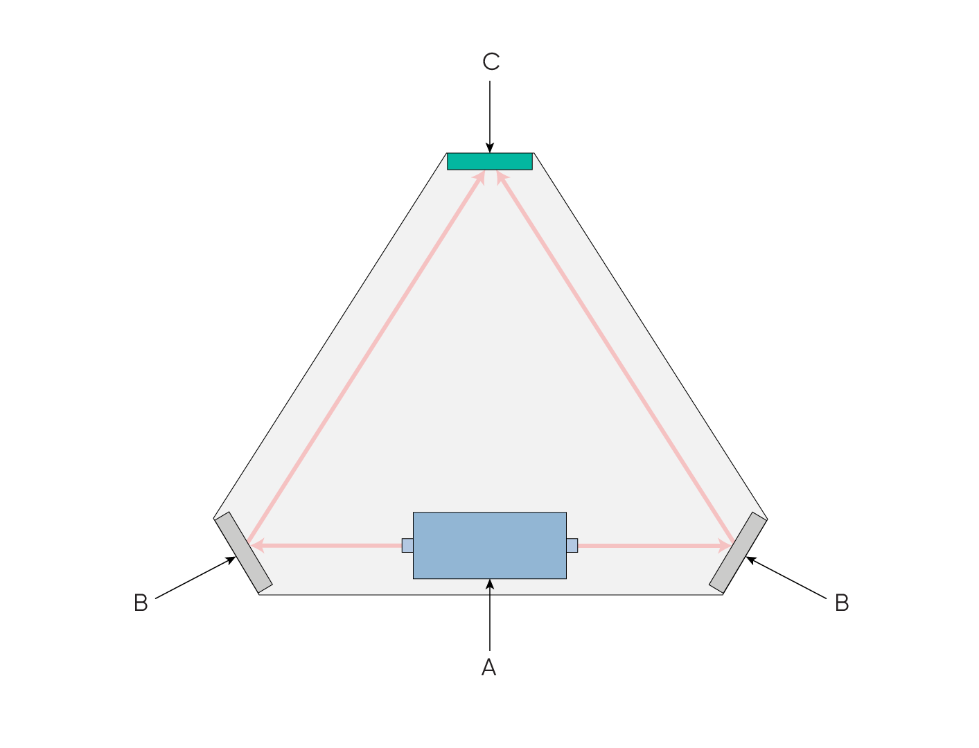
Image depicting the basic operation of a ring laser gyroscope. A laser source (A) emits beams of light simultaneously in opposite directions. The light bounces off mirrors (B) that direct it to an optical receiver (C). Any rotation of the device will cause the light beams to reach the optical receiver at different times due to the Sagnac effect, which can be extrapolated into a measurement of rotation
A typical RLG uses two laser beams that are sent in opposite directions along a path that is defined by mirrors. The laser light reflects from one mirror to the next, creating the “ring”, until reaching the optical receiver. The ring laser gyroscope measures the frequency difference between the two light waveforms to define angular velocity.
It can be said that FOG is superior to RLG, mainly due to the longer light path making it capable of providing a higher resolution of measurement. The RLG, however, has been in production and use for several decades longer than FOG and this has made it a long established gyroscope technology in various industries, such as commercial aircraft manufacturing.
Single-Axis and Hybrid Optical-MEMS Gyroscopes
Some FOGs and RLGs may be built for single axis rotation measurement only, which will typically be for use in applications that require precise heading measurement (rotation about the Z-axis); for example, ships and submarines. Other designs may use a hybrid setup of gyroscopes to reduce cost, size and weight. Typically in such cases, the optical gyro will be for heading, with cheaper, smaller and less accurate MEMS gyros for roll (X-axis) and pitch (Y-axis) rotation measurement.
Recent Tech Articles

High-Precision Navigation at Scale for Counter Drone Technology
Unlock precision for your kinetic effector on-the-move. Discover how Advanced Navigation delivers the stabilization and supply chain speed needed for scalable counter drone defense.
18 May 2026
Go to Article
Navigating the Future of Mining Operations
Discover how to improve product quality in manufacturing through Advanced Navigation's rigorous supply chain and exhaustive validation.
5 May 2026
Go to Article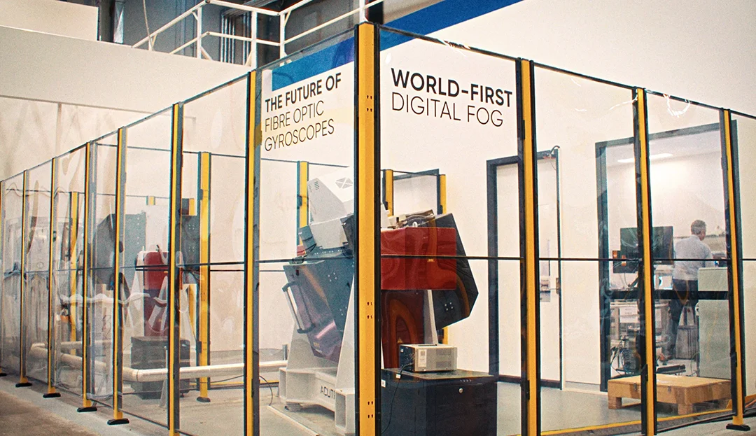
How Advanced Navigation’s Manufacturing Ensures Consistent Product Quality
Discover how to improve product quality in manufacturing through Advanced Navigation's rigorous supply chain and exhaustive validation.
27 April 2026
Go to Article