Tech Article
Published on:
There are several techniques for using USBL that are suited to different applications, each of which provides different advantages and results. USBL-squared (USBL2) is unique to Advanced Navigation. This article briefly explains each technique and the benefits of USBL-squared to help untangle any confusion on the subject.
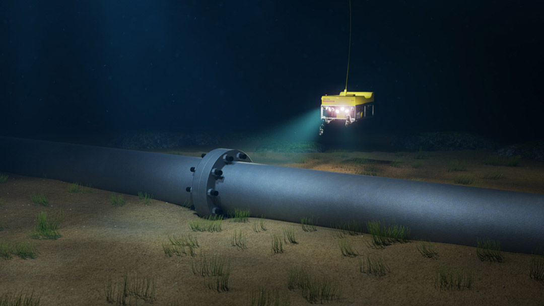
Finding something and keeping track of it underwater is very difficult. Once we submerge an object, like a remotely operated vehicle (ROV), as it descends it will soon become unseen and unheard and its position unknown. An ROV may be able to illuminate the area around it and have cameras that stream video via tether to a pilot aboard a surface vessel, however, position and orientation are not known with any certainty.
USBL is a system that uses acoustics (sound waves) to measure range and direction (“bearing”) between a vessel and a tracked object. Acoustics are used because the density of water is largely impenetrable to radio and light waves and this severely restricts wireless communications. For more information on USBL and how it works, read our article on Acoustic positioning and navigation – an introduction.
This is the traditional implementation of USBL, with a transducer mounted near the water surface (usually attached to a surface vessel) and one or more transponders down in the depths. The transponders may be attached to tracked objects or set in fixed positions.
A transducer will usually have the ability to receive absolute position information from the surface vessel navigation system or a simple dedicated GNSS receiver setup mounted to the boat and a vessel mounted gyroscope for motion analysis. The transducer, GNSS, and vessel mounted gyroscope are then calibrated into their installed location. With this information, the transducer knows where it is in the world and also which direction it is pointing.
Firstly, the transducer sends out an interrogation signal that the transponder is designed to respond to. When the transducer receives an acoustic response ping from a transponder, it will calculate a range to the transponder and the direction from which the acoustic signal has come. The range is calculated using the two-way travel time of the sound wave through the water. This provides a range to the transponder, with USBL determining the bearing of the acoustic source relative to the transducer. The transducer knows its location and applies this to the relative position of the transponder to provide an absolute position to the transponder.
In this configuration, a reasonably accurate position of the transponder can be attained, however, motion data for the tracked object can be based only on the recorded location that is logged at each ping cycle. Motion of the tracked object is like a join-the-dots puzzle, where each dot represents a ping cycle and the straight lines between the dots is the presumed/extrapolated (not captured) motion. Post-processing of the data points utilizing proprietary algorithms and/or Fourier analysis can yield extrapolated estimations of the tracked object’s motion. Heading of the tracked object remains largely unknown, however, and can only be inferred based on the movement of the tracked object between ping cycles. For applications where a simple ping and location fix for transponders is required, classic USBL is a proven solution.
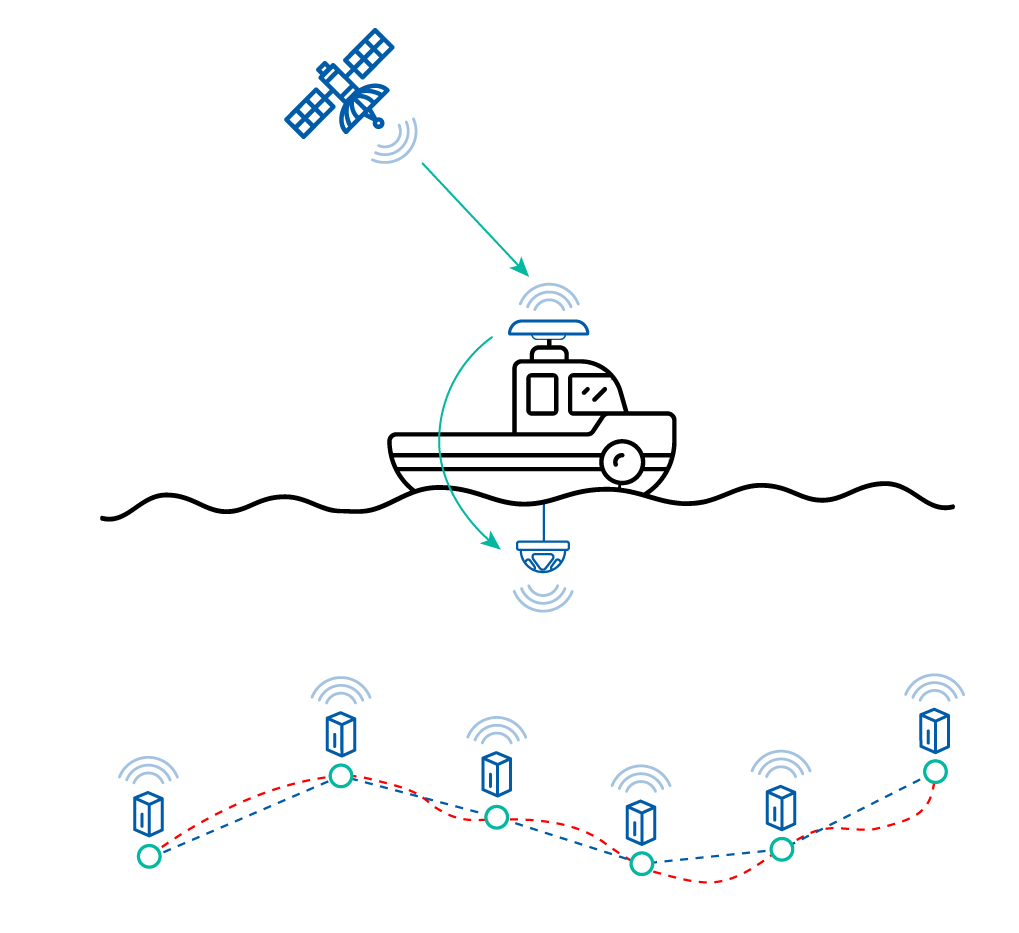
Image depicting classic USBL operation, where a transducer at the surface vessel emits an acoustic ping. Transponders that detect the ping, emit a ping back. The return ping is processed to provide range and direction information of the transponder. Position is attained at each ping only, so motion data between pings is not logged. In the example, the green circles are the pings, the red line is the [unknown] actual path of motion, the blue line is the estimated travel path. Heading of the tracked object is relatively unknown
Inverted USBL, as the name suggests, is a reversal of the physical locations of the transducer and transponder. The technique for resolving the location of the transponder to the transducer is identical to classic USBL, however, the transducer now resides on the tracked object.
The obvious question here is why invert the USBL? The answer is to provide superior motion data for the tracked object and also to reduce the effect of surface vessel interference on the USBL. The update frequency or refresh rate of the inertial sensors within a typical USBL transducer is perhaps several hundred times per second, rather than a location ping for the tracked object once per second of classic USBL. This means that a lot more motion data for the tracked object is being logged and processed. If you were to think of an old-fashioned radar screen, the tracked object would create a blip on the screen at a different position at each sweep of the radar. What happens to the blip in between each radar sweep is unknown. Inverted USBL overcomes this by providing a much more comprehensive record of motion for the tracked object.
In the case of iUSBL, the transducer is way down in the water and typically well away from boat engines and other sources of noise that can affect USBL acoustic signal quality. This can improve communications and may reduce the slant range error of the system. A submerged transducer may not have immediate access to an absolute positioning source, so heading is usually provided by a gyrocompass mounted to the tracked object; in high precision applications, this would typically be an inertial navigation system (INS). Popularly today a fibre-optic gyroscope (FOG) INS is used.
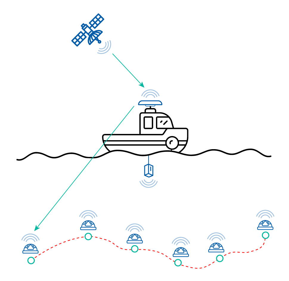
Image depicting inverted USBL operation, where a transducer is mounted to the tracked object, and a transponder is attached to the surface vessel. The transducer emits an acoustic ping that is returned by the surface vessel transponder. The return ping is processed to provide range and direction information to the transponder. Location of the transponder may be provided by additional means, such as via tether from the surface vessel. Position is attained at each ping cycle, however, full motion data between pings is also being logged. In the example, the green circles are the pings, the red line is the logged path of motion. Heading of the tracked object is typically provided by a gyrocompass, FOG or similar
Another option for the inverted USBL configuration is to use several transponders, set at fixed locations to create a baseline along the vessel’s hull or other structure.. The transponder locations are programmed into the navigation system, so that when acoustic signals are received from the transponders, the navigation system can quickly calculate its position by triangulating the acoustic sources. This method may also be used to derive heading relative to the fixed transponders. Because the transponders are fixed in position, however, the application of this type of iUSBL may be somewhat limited.
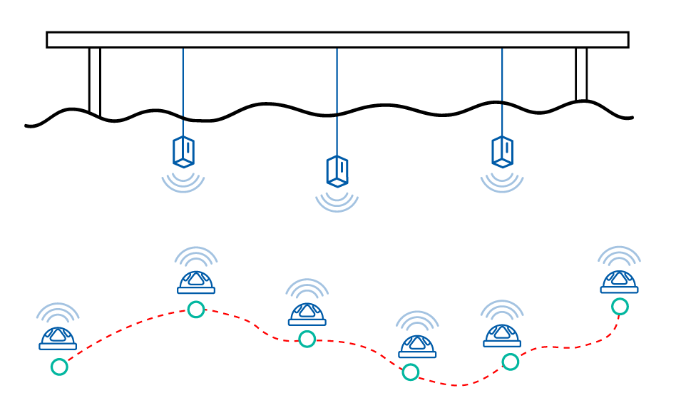
Image depicting inverted USBL operation, where a transducer is mounted to the tracked object, and multiple transponders are set at fixed positions near the water surface. The transducer emits an acoustic ping that is returned by the surface transponders. The return pings are processed to provide range and direction information to the transponders. Position is attained at each ping, however, full motion data between pings is being logged. In the example, the green circles are the pings, the red line is the logged path of motion. Heading of the tracked object is calculated by resolving the vector between each transponder and the transducer
The Advanced Navigation Subsonus USBL solution provides a third, unique USBL configuration option called “USBL-squared” (USBL2). The primary difference to other USBL configurations is having a transducer on both surface vessel and tracked object. If you consider classic USBL and inverted USBL as having the location of the transducer as the primary differentiator for certain performance reasons, it becomes clear that having a multi-transducer setup will offer significant advantages.
The Subsonus transducer contains a high specification inertial navigation system (INS) alongside its hydrophone array and acoustic sounder. These elements are pre calibrated during manufacturing, reducing in-field calibration time for operators. The INS provides roll, pitch, magnetic and gyroscopic heading, heave and acceleration data of the unit, allowing high accuracy dead-reckoning capability in full six-degrees of freedom (6DoF). Data from the inertial sensors is fused and processed using AI-enhanced algorithm technology. The hydrophone array is also used to measure the speed of sound through water at the transducer head.
The acoustic signals in the Subsonus USBL system are encoded with data and contain multipath rejection filters inherent to the acoustic signaling. This allows information to be shared between the transducers, rather than a simple ping-response-fix scenario. To initiate the USBL2 system, the surface vessel Subsonus will emit an acoustic signal that the remote Subsonus will respond to. The surface vessel Subsonus will resolve the range and bearing of the remote unit and then acoustically send the absolute position and heading of the remote Subsonus to that transducer. Now, the remote Subsonus knows where it is in the world and in which direction it is headed. Additionally to this, the magnetic and gyroscopic heading sensors of the remote Subsonus are fused into the acoustically derived heading.
The above features enable the system to resolve magnetic heading drift caused by interference and gyroscopic drift by constraining them against each other and the absolute heading data provided by the surface transducer. The remote transducer derives relative heading to the surface unit, but because it can reference this against the absolute heading data provided by the surface transducer, can resolve its absolute heading with a very high level of reliability and accuracy. The result of this is that the INS of the remote Subsonus becomes a source of absolute heading that we refer to as “acoustic compass”.
This functionality enables the USBL-squared system to be not only a high accuracy subsea positioning and heading system, but it is also immune to the effects of latitude (secLat degradation), making it an extremely effective heading system at very high latitudes. To illustrate, as latitude increases, the effective circumference of the Earth reduces to the point where, when at the actual axis of Earth’s rotation (geographic poles), no rotation can be detected. For fibre-optic gyroscopes, this reduction in effective circumference is an issue – the greater the latitude, the less they are able to accurately determine angular rotation and, therefore, heading accuracy progressively declines.
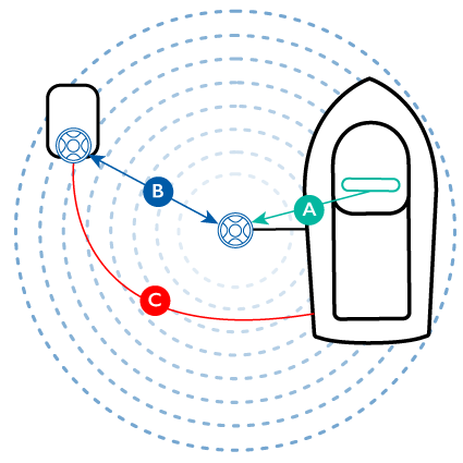
Image depicting how position and heading for a Subsonus transducer on an ROV is derived. Absolute position and heading data (A) of the vessel is provided by a satellite compass or other heading system input (for example, GNSS Compass) that connects to the surface vessel Subsonus. The surface vessel Subsonus pings the remote Subsonus to determine its relative position and provides this data (B) acoustically and via tether to the ROV Subsonus. The ROV Subsonus then determines its absolute position and heading from the bearing fix and sends navigational data (C) back to the head system via the tether
Acoustic transfer of data between the Subsonus units occurs approximately once per second (1 Hz). It should be noted that the frequency of data sharing depends on the number of remote Subsonus units in use and the slant range of the tracked units. The continuous transfer and processing of USBL, INS and GNSS data at each Subsonus transducer delivers very accurate and reliable performance.
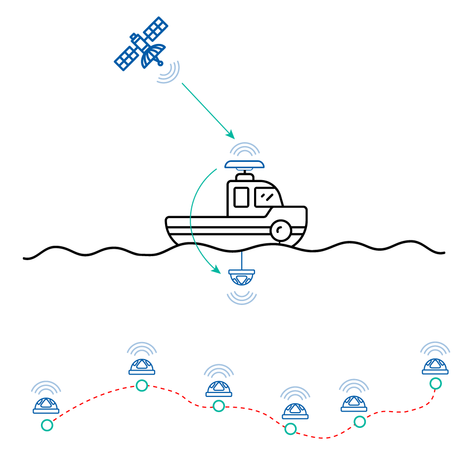
Image depicting Subsonus USBL2 operation, where the surface vessel Subsonus transducer is connected to a satellite compass for GNSS derived absolute position and heading input. Location of the remote Subsonus is attained acoustically, then resolved to absolute position and heading, which is then shared with the remote Subsonus. Navigation data is constantly exchanged between the Subsonus units to maintain the highest accuracy and precision possible. Position is attained at each ping, however, full motion data between pings is being logged. In the example, the green circles are the pings, the red line is the logged path of motion. Heading of the tracked object is derived through USBL calculations being made at both surface vessel and tracked object without the need for additional hardware, such as a FOG
Advanced Navigation’s USBL2 heading and positioning solution opens new possibilities for applications that use USBL. The multi-transducer USBL2 architecture greatly simplifies and reduces the costs and complexity involved with capturing full high-accuracy motion data of underwater tracked objects and delivers unprecedented availability in shallow and difficult water conditions.

20 May 2025
Go to Article
30 March 2025
Go to Article