MEMS VS FOG: What Inertial System Should You Choose?
Share:
Published on:
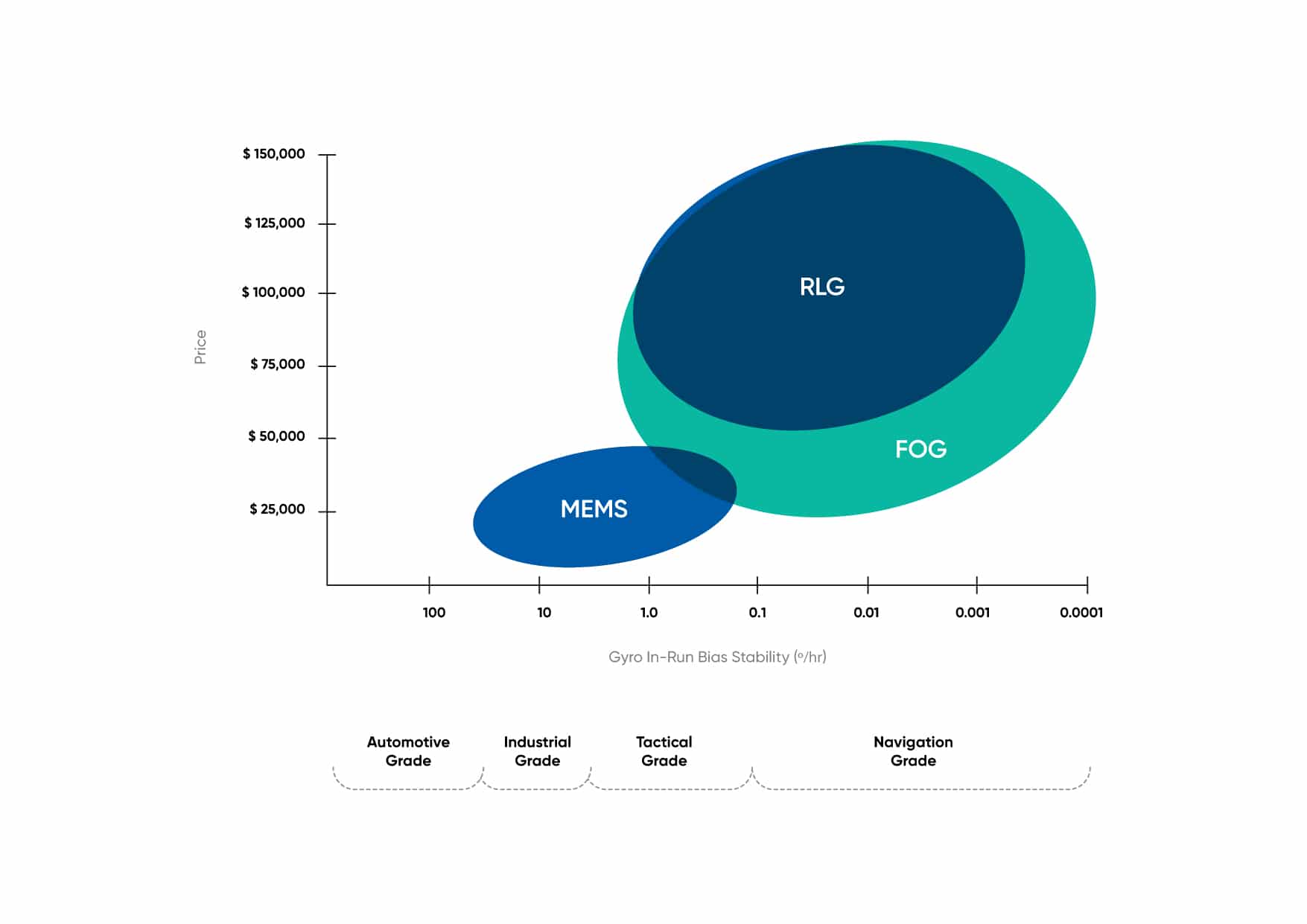
MEMS vs FOG: the Ring laser gyroscope (RLG) has dominated the inertial navigation market since its first inception in 1963, recently its dominance has been challenged by improvements to Fibre Optic Gyroscope (FOG) technology. These technological improvements are slowly but surely eroding the RLG’s place in the inertial navigation market, pushing the aging technology to irrelevance.
Is this cycle about to be repeated with MEMS?
This is a legitimate question, given how far the technology has come in recent years, with MEMS gyro sensors achieving better accuracy, improved error characteristics, and better g-sensitivity, that has drastically improved overall MEMS performance. The two technologies now often go head-to-head for numerous tactical and navigation grade applications.
Picking an inertial technology used to be a straightforward decision, but as the competition between the two technologies heats up, navigation engineers are forced to pay closer attention to factors such as SWaP-C (Size, Weight, Power and Cost) for their specific application before settling for either solution.
FOG Still Dominating for Critical Applications
Fibre has become the tried and tested solution for high-end applications, slowly replacing the aging RLG technology. The technology offers unmatched performance, thanks to its very low noise fibre-optic gyroscopes, enabling extremely accurate navigation, and low bias instability and drift relative to other technologies, essential to staying on track in GNSS denied environments.
FOG INS is considered better suited for critical navigation solutions such as deep-sea underwater navigation and aerospace applications. While its higher cost makes it prohibitive for the lower end of the market, less price-sensitive end-users such as the military and commercial aircraft manufacturers will afford the increased accuracy. FOGs inherent lower drift also makes it the preferred choice for long-term GNSS denied applications, as the overall error is lower than even the most accurate MEMS INS available.
Another feature unique to FOGs that makes this technology so attractive is its north-seeking capabilities. FOG precisely measures the earth’s angular rate of rotation, even while being in motion, and are able to accurately determine north and achieve a gyrocompass heading within minutes. This is a particularly sought-after feature for subsea applications that cannot rely on any GPS signal for long periods of time. Conversely, MEMS technology does not have sufficient gyroscope accuracy, and relies on magnetometers or dual antenna GNSS to get accurate heading.
Both FOG and MEMS accuracy are impacted by variations in temperature. This problem is typically mitigated by calibrating the system across the operating temperature range. MEMS technology is highly sensitive to temperature fluctuations, which require careful temperature compensation. By contrast, a well designed FOG, properly insulated and calibrated, will generally perform better.
Finally, whilst FOG INSs are not immune to errors in vibration-prone environments, because FOGs do not have any moving parts, they can handle vibrations better than their MEMS counterpart. FOG is therefore the preferred approach with heavy equipment stablization for mining and industrial applications and aerospace, where aircraft, and notably their wings, are subjected to a very high level of vibration.
MEMS Closing the Gap Between Price and Performance
Micro-electromechanical systems (or MEMS) have made rapid advances since their introduction in the 1950s. Made of tiny integrated circuits and silicon-based microelectronics, the technology has dramatically revolutionized industrial and consumer electronics alike. For inertial measurement units and inertial navigation systems, MEMS technology saw the creation of a variety of inertial sensors, including gyroscopes, accelerometers, and magnetometers.
By far, the main benefit of MEMS is its extremely low cost compared to its FOG counterparts, usually by a factor of mora than 10. The use of less expensive materials, advanced manufacturing processes, smaller size, and mass adoption, have all contributed to MEMS being cheaper to produce. Today, it is widely used in applications ranging from in-car GPS, drones, or camera pointing, where FOG technology is simply too cost-prohibitive to make commercial sense.
MEMS devices are also very small and lightweight, allowing them to be used in tight spaces such as smartphones and toys. MEMS are now found everywhere, from consumer to industrial-grade applications in a wide range of industries. This small form factor notably fueled the adoption of MEMS in the drone surveying market, notably LiDAR surveying, where a higher degree of accuracy is needed while remaining relatively small and lightweight in order to fit on a drone. By contrast, FOGs are considerably larger and heavier, thus reducing the number of suitable applications.
MEMS are also less power-hungry than FOGs, allowing for longer mission times for energy constrained vehicles. Combined with their small size and lightweight properties, MEMS is the solution of choice for many unmanned vehicles that require the lowest SWaP-C (size, weight, power, and cost).
MEMS though is not without its limitations. Due to its mechanical nature and components vibrating at a high frequency, MEMS are more sensitive to vibrations, especially at harmonic frequencies. Vibrations can increase the noise of a sensors output signal, causing a bias that needs to be corrected via software.
This issue can have some practical consequences. A non-negligible number of drone gyroscopes have been found to have resonant frequencies in both the audible and ultrasonic frequency ranges, making them vulnerable to loudspeaker noises. Therefore, it is possible to crash a drone at distance via a “sonic attack” using speakers set at the right frequency.
MEMS are also typically prone to g-sensitivity errors in gyroscope measurements due to linear acceleration, leading to large biases directly affecting the accuracy of attitude estimation in an INS. While acceleration is often short – just a few seconds – but intense – 5g or more in highly-dynamic fields such as unmanned aerial vehicles, the accumulation of errors over time cannot be neglected, and need to be compensated for. Corrections are done at the filter level but add another degree of complexity that FOG alternatives are less susceptible to.
The MEMS vs FOG Verdict
FOG and MEMS solutions cannot always be easily compared with each other, as the trade off in price and performance can still be quite vast. However, when comparing low-end FOG with high-end MEMS, the appeal of MEMS for size, weight, power and cost, vs a small increase in performance can be appealing.
Ultimately, of the two systems, FOG will always offer the highest level of performance possible. The real question is: can your budget stretch to the desired performance level, and can the increase and size, weight and power be accommodated within the application.
Criteria
| Criteria | MEMS | FOG |
| Bias Instability | Good | Best |
| Initial Bias | Poor | Excellent |
| Size | Small | Larger |
| Power | Low | Moderate |
| Heading | Magnetic | North Seeking / Gyrocompassing |
| Magnetic Interference | Yes | No |
| Acceleration & Vibration | Good | Best |
| G-Force Error | Yes | No |
| Price | Lowest | Highest |
Applications
| Application | MEMS | FOG |
| Drone/UAV | Small payload, cost sensitive, low power, small size | |
| Subsea | Best attitude accuracy, north-seeking, better bias stability | |
| Aircraft | Better bias stability | |
| Ground Vehicle | Cheaper, good performance for many application | Best for high accuracy surveying and long GNSS outages |
| Marine | Easy set up (e.g. with GNSS Compass) | Best attitude accuracy, north-seeking, bias stability |
| Car Racing | Smaller, lower power, good g-resistance | |
| Surveying | Small size, low power | Best performance |
Recent Tech Articles
How Improved Positional Accuracy Can Transform Mining Excavation
Explore the new standard in absolute positioning for GNSS-denied environments. See how the Chimera Land LVS and INS pairing anchors real machine motion.
15 June 2026
Go to Article
High-Precision Navigation at Scale for Counter Drone Technology
Unlock precision for your kinetic effector on-the-move. Discover how Advanced Navigation delivers the stabilization and supply chain speed needed for scalable counter drone defense.
18 May 2026
Go to Article
Navigating the Future of Mining Operations
Discover how to improve product quality in manufacturing through Advanced Navigation's rigorous supply chain and exhaustive validation.
5 May 2026
Go to Article