Tech Article
Published on:
The genealogy of lidar (light detection and ranging) stems from sonar (sonic navigation and ranging) and radar (radio detection and ranging) technologies. Sonar and radar use acoustic (sound) and electromagnetic waves in the radio or microwave frequency spectrum, respectively. Lidar technology uses electromagnetic radiation in the infra-red and visible light spectrum, which are much higher frequencies than that of radio or microwaves.
The primary purpose of the three technologies is to detect and measure the distance to objects or surfaces through wave reflection and detection. Each system uses a high-accuracy timing device to measure how long it takes from the time that the emitted energy, be it sound or electromagnetic radiation, to travel both to and from the object or surface. Using this duration and the speed of the sound/radiation, the range can be accurately calculated.
Lidar uses laser technology to emit light (photons) that has the necessary wavelength to suit the desired purpose. The beauty of laser technology is that it is capable of emitting light with extreme consistency; that is, in terms of its wavelength, polarization and direction, over time. These properties enable the laser beam to have a very narrow range of wavelengths, giving it a distinct, singular (monochromatic) color (if visible light) and for it to be very tightly focussed, which creates the classic long and narrow beam of light, rather than one that spreads out in all directions.
Laser wavelength is inversely proportional to the frequency and, because the speed of light in any given medium is constant, knowing one means you can determine the other. In a lidar application, the desired propagation and reflective properties of the laser will determine the wavelength / frequency to use. For example, if the lidar is being used to detect the particle concentration of a specific gas in the atmosphere, the laser wavelength must be reflective of the target particles.
The power of the laser is also very important in lidar surveying applications and can be correlated to the maximum distance away from the lidar that objects can be detected. The higher the output power of the laser, the farther away the lidar can be from detectable objects. In UAV-lidar surveying, a higher-powered lidar scanner can be used at greater distances AGL (above ground level) / altitude. Increases in AGL increase the swath width of the scanned area for each pass, making for faster scanning of the survey area. Note that laser power in typical lidar surveying applications is limited by eye safety regulations.
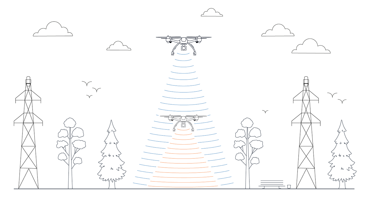
Image depicting the increase in swath width when UAV-lidar surveying at higher altitudes, enabled through using higher power lidar scanning lasers. An additional benefit is that the UAV can be used at altitudes that make them less prone to collisions with trees and power lines, for example
The extremely short wavelength of a typical lidar laser makes the actual beam itself a very small diameter. This small size enables a lidar scanner to produce very high-resolution / high density data due to the sheer number of laser emissions and reflections that it can produce. The generated data, which is essentially the range information for each emission/reflection, is known as a point cloud.
Our hunger for data has never been stronger than it is now. The quest to acquire data for research, knowledge, and understanding is spurring many great advances in sensors and other technologies that allow us to detect and measure things remotely and in automated ways that not so long ago were limited purely to the imagination.
Lidar is such a technology. Lidar allows us to capture information about a site, object or landscape that can be represented in a highly visual way – a point cloud map, 3D mesh or model that we can analyze to understand and estimate various conditions and characteristics of the survey site. A point cloud may contain many, many millions of reflected laser points, with each point accurately referenced to absolute position (longitude and latitude coordinates) on the Earth’s surface. This mosaic of points can produce a very detailed and accurate digital twin of the survey site. Point cloud maps and models will typically apply color gradients to represent variations in range of the reflected light to the scanner, making human interpretation very intuitive. This makes the output of lidar surveying invaluable to clients that, without a readily understandable graphical model, may be otherwise unable to interpret the data.
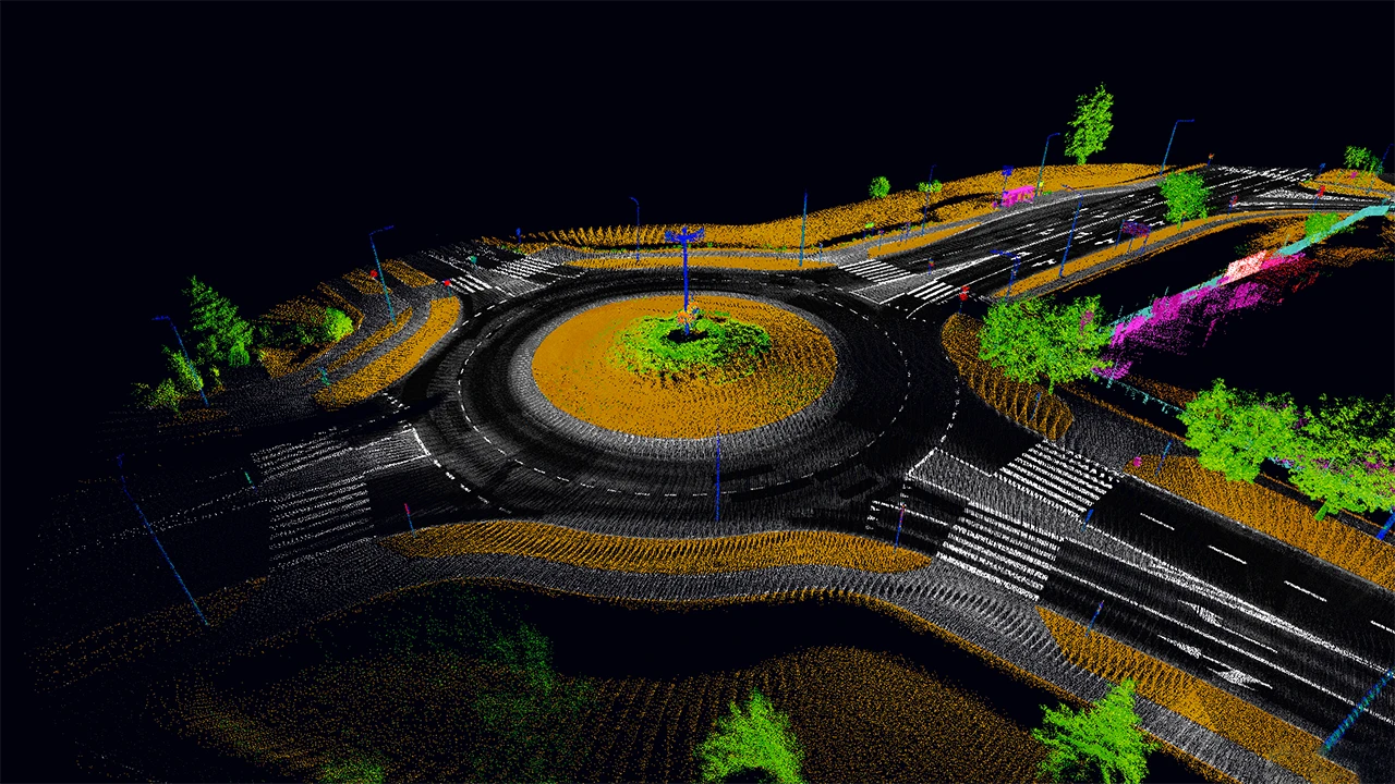
Example lidar survey point cloud. Image courtesy EyeVi Technologies
Something quite peculiar to lidar is that a laser emission may be able to have multiple reflections, depending on survey site conditions and angle of laser penetration. A good example of the benefits of this over, say, photogrammetric (photographic image based) surveys, is that lidar is able to filter through vegetation to an extent, in much the same way that light filters down through a forest canopy to the forest floor, and is capable of receiving multiple reflections from the same emission. That is, some photons will reflect off part of a leaf, for instance, others a branch, and some photons bouncing off the ground surface. The amount of energy in the reflected light (the number of photons or the intensity of the reflected light) usually determines some property of the object or surface; for example, its opacity, shape, material and absorption of light. With our forest example, this means that distance to the ground surface can be measured as well as the distance to treetops and objects in-between, making lidar an exceptional tool for topographical survey of densely vegetated areas.

Example image shows how a laser emission passing through a tree may provide multiple reflections as parts of the laser beam encounter various objects, including the ground surface
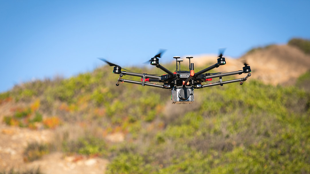
In the interests of keeping in theme with small-scale and more affordable commercial applications of lidar surveying, we will ignore lidar surveying from piloted aircraft and concentrate on UAVs (uncrewed / unmanned aerial vehicles) or “drones”.
The UAV has been around a lot longer than might be imagined, however, since 2006, UAVs entered the commercial space and a few years later were introduced into the personal market. The explosion of UAV drone use since, which some describe as a “drone revolution”, has been instrumental in making lidar surveying what it is today. The fact that a drone can typically travel in any direction as well as hover with high levels of control and stability makes it extremely well suited to surveying and inspection both in, around, and under structures as well as from above.
It is fairly safe to say that the evolution of lidar, since it first appeared in the 1960s, has accelerated since GNSS (global navigation satellite system) receivers and inertial measurement units (IMUs) became commercially available in the 1980s. GNSS and IMU technology enables high accuracy satellite-based navigation and a detailed understanding of vehicle motion that, together, opens up a new world of possibilities for the UAV. If you couple UAV drones and inertial navigation systems and lidar, the result is a vehicle that is easily and relatively cheaply deployed that can provide outstanding results for mapping the surroundings, georeferenced to absolute position on the Earth’s surface.
The cost of lidar scanners is reducing, as is the physical size and weight as the technology further advances. In conjunction with this is increasing scanning speed and the resulting survey resolution. Currently, the fastest scanners can operate at a staggering two million points per second and even more, providing exceptionally detailed point clouds. Similarly, the ranging distance of lidar scanners is increasing, allowing the scanner to be used at higher altitudes or further from the survey site whilst still producing acceptable results.
The speed at which high-resolution UAV-lidar surveying can be carried out and its versatility has many benefits over traditional surveying techniques, such as:
Applications for lidar continue extending far beyond aerial topographical survey. In fact, if there is anything that requires visual inspection, it is quite possible that a lidar based solution is available or likely will become available.
The beauty of lidar technology is that it lends itself to a tremendous array of applications that have traditionally required very large amounts of labour and time and associated costs. Below are some examples:
The emerging autonomy revolution and the idea of automating tasks that are labour-intensive, hazardous or otherwise inefficient for humans to perform, is driving deep innovation in many diverse fields and applications. The notion of combining lightweight and uncrewed aerial vehicles with satellite navigation, lidar and inertial navigation systems continues to provide excellent tools for survey and inspection that is hard to beat, so what improvements might we see?
Artificial intelligence (AI) and machine learning (ML) software are technologies that can be used with lidar to great success. As lidar resolutions increase, the ability for object identification and classification also goes up. AI/ML software is typically “trained” in the lab to recognize objects, creatures or phenomenon by characteristics of shape and size. Moreover, complex automated analysis is becoming possible with increased lidar point cloud resolution that enables more complex shapes and smaller sized objects to be recongizable.
New and improved remote sensing technologies are rapidly increasing the spectrum of data acquisition. For example, hyperspectral imaging of atmospheric and ground-based chemical composition for agricultural use. By fusing information from third-party sensors with lidar and navigation data, the resulting survey point clouds can include a gamut of sensor data that makes analysis of multiple phenomena possible. It is also becoming more common to gather multiple data types in a single survey rather than multiple surveys using different sensing equipment, which saves time, reduces cost to clients and minimizes emissions.

20 May 2025
Go to Article
30 March 2025
Go to Article