Inertial Guidance: A Brief History and Overview
Share:
Published on:
Table of Contents
- Introduction
- Why Use Inertial Guidance and Inertial Navigation Systems?
- What Are Inertial Guidance and Inertial Navigation Systems?
- The Future of Inertial Guidance
Introduction
We understand the concept of navigation as a means of getting from one location to another. For example, a hiker being given instructions to reach a particular destination – turn left at the second trail, then take the third trail on your right, walk about 2 km and you should be at the waterfall! Each point of reference in the journey is a way-point that is used to ensure you are following the correct path. The trail walker’s route is simple as it uses readily identifiable physical way-points – the start point where the instructions were given, the junctions on the trail, and the waterfall.
Modern navigation uses a Cartesian coordinate system that basically enables pinpointing a two-dimensional location on the Earth’s surface using a numbered grid. The Y-axis (latitude) starts at the equator and X-axis (longitude) starts at the Greenwich meridian. The Greenwich meridian is a hypothetical plane between the south and north poles that passes through the Royal Observatory in Greenwich, UK. This particular location was adopted as the international reference meridian for navigation well over 100 years ago. In the pre-Cartesian model era, maritime navigators would rely on visible landmarks if near shore or celestial objects (the sun and certain stars) when out at sea, as references. This means of navigation, although a little crude by today’s standards, served the purposes of traversing sea and land for centuries.
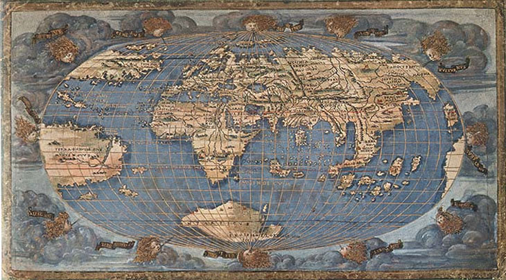
World Map (1508) by Francesco Rosselli – This is one of the first printed maps to chart the globe within a cartographical grid, spanning 360 degrees of longitude and 180 degrees of latitude. National Maritime Museum, Greenwich, London.
The limitation of most navigation systems is the need for references to confirm actual position with estimated position, be it a map, a star, a satellite constellation, or a landmark. When a reference is not available, we require a different means of maintaining navigation and guidance. Using inertia as a means of detecting and measuring changes in motion has been a popular method of unaided navigation.
Why Use Inertial Guidance and Inertial Navigation Systems?
With the availability of maps and other means of navigating, why do we need inertial guidance? The short answer to this question is autonomy. An “autonomy revolution” is at hand, where the combination of various technologies and artificial intelligence (AI) is beginning to really impact various industries in profound ways to save labour and safely increase productivity. A good example is autonomous farming. The growing use of autonomous systems and the key requirement of navigation is pushing the industry into developing fully unaided, truly autonomous, navigation systems.
An uncrewed vehicle generally requires remote control of some sort or is autonomous and uses an on-board guidance system to navigate. Rockets were likely the stimulus for research in the field of autonomous guidance systems, particularly after Prof. Robert Goddard, an American physicist and inventor, demonstrated the first apparent liquid fuel powered rocket in 1926. Goddard’s rocket engine did not require oxygen so could operate in a vacuum and this opened the doorway to the current age of space exploration, even if this may have seemed somewhat absurd at the time. Goddard’s continued intrigue in rocket propulsion and designing a system that could actually escape Earth’s gravity became even more heightened and he is accredited with a great many innovations in rocket science. Prior to this point in time, rockets had existed for hundreds of years, many propelled by gun powder, and have been used for entertainment in the form of fireworks and as military assault weapons – for instance, fire the rocket towards the adversary and, with some luck, create a fire in enemy territory.
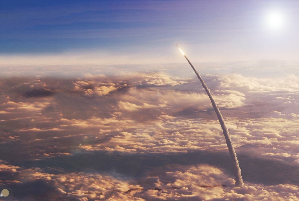
Image of a rocket flying high above the clouds and about to pass through Earth’s upper atmosphere. Note the non-linear trajectory of the vehicle.
Until very recently, a rocket has been considered single use and, as a result, typically does not have human pilots and all of the extra equipment required to keep them alive and awake. For this reason, and the fact that a rocket is subjected to very high accelerative loads, travels very quickly and can be huge distances away from Earth, an on-board navigation system was considered essential. A space rocket is generally tube shaped with very little protuberances in the form of wings and rudders (useless in space as there is no atmosphere). This tends to make the vehicle less stable than, say, a fixed wing aircraft with multiple wings and a broad wingspan. An inherently unstable design requires a navigation system that is capable of fast and accurate response to rapid fluctuations in heading. The quest for an independent and accurate self-contained navigation system began, with Goddard himself also pioneering the use of mechanical gyroscopes and directable thrust to enable some amount of self-guidance.
Military requirements latched on to the idea of self-guided rockets and ballistic missiles. The German V-1 and V-2 rockets of world war II are probably the most widely known as the first long-range self-guided ballistic missiles, using liquid fuel propulsion, gyroscopic navigation and directable thrust. The V-2 also became the first man-made object to reach space. From this point, efforts into perfecting rockets and guidance systems continued in earnest, with the aim to develop both large and small rockets, increased destructive power, cheaper production, and more accurate guidance systems. Of course, there were also the space rocket programs of the USSR and US to “put man on the Moon”.
Rockets, Satellites and GNSS
Rocket technology enabled humans to break out of Earth’s atmosphere and this led to the advent of satellites for scientific research and assisting communications on Earth. The rapid adoption of satellites for various tasks led to using them being built and placed into orbit specifically for navigation purposes. This began approximately 50 years ago with GPS (global positioning system), initially for US defense purposes, that is now part of a truly worldwide navigational satellite network – GNSS (global navigation satellite system).
Navigational satellites are set in very specific orbits approximately 20000 km above the Earth. Each satellite constantly broadcasts signals that identify the satellite, its orbital position, time and other data. GNSS receivers on Earth use the signals from four or more satellites to calculate a three-dimensional (X-Y coordinates plus altitude (Z)) location on Earth, based on the distances between the receiver and each satellite.
Is Inertial Guidance Necessary when we have GNSS?
The success of satellite based navigation has made it so widespread that it is used in a great many aspects of our lives now. Modern technologies that use GNSS are capable of very accurate positioning, practically anywhere in the world and no map as such is required. Somewhat conversely to this, the reliance on GNSS has also made it a vulnerability in that it can be spoofed and tampered with, or not available and this meant developing alternative navigation systems that can operate independently of GNSS. For example, what if…
- We need to understand the motion of a vehicle without necessarily having to use a coordinate system and GNSS to determine location and way-points?
- We want to construct a self-guided aerial vehicle that is immune to satellite signal interference and tampering?
- We want to build an underwater vehicle that can reliably and safely navigate the deepest waters without any GNSS?
- We want to make autonomous vehicles that can safely operate underground?
A common answer to these questions is to apply inertial guidance using an inertial navigation system (INS).
The limitation of most navigation systems is the need for references to confirm actual position with estimated position, be it a map, a star, a satellite constellation, or a landmark. When a reference is not available, we require a different means of maintaining navigation and guidance. Using inertia as a means of detecting and measuring changes in motion has been a popular method of unaided navigation.
What Are Inertial Guidance and Inertial Navigation Systems?
Inertial guidance and inertial navigation use the concept of determining the course of a vehicle by detecting and measuring inertia, which are forces created due to an object’s resistance to changing direction. That is, whenever the object is subject to an acceleration, the detected rates of acceleration and duration in each axis is measured and processed into a vector that describes the motion of the object. To measure inertia accurately requires sensitive equipment and this presents many engineering challenges.
As with many emergent technologies, first attempts at inertial guidance and navigation systems were large, expensive, heavy and cumbersome. Early systems used large, mechanical gyroscopes that required complex support frames and housings, making them unsuitable for many practical applications. The birth of the integrated circuit in the 1960s and the ensuing progress in miniaturization using silicon material to shrink complex electrical circuits from large PCBs with vast numbers of components down to postage stamp sized chips led to the development of micro-electromechanical systems (MEMS) components.
MEMS are tiny devices that are often a combination of electrical and mechanical elements that are designed to provide a specific function. For example, a MEMS-based accelerometer has a part that moves when subjected to acceleration. MEMS devices are well suited to building highly sensitive components that can detect wide ranges of inertia. This led to very significant reductions in size, complexity and costs for inertial navigation systems, making them eminently more suitable to a much broader range of applications. There are several technologies in use, with many options available for detecting linear acceleration and changes in angular velocity, detecting the Earth’s magnetic field for deriving heading, and measuring pressure and altitude. Data from the INS can be used by a vehicle control system to estimate, adjust or correct course without necessarily requiring communications with a third-party control system on the ground or requiring a GNSS fix, for example.
The core component of an inertial guidance system or INS is the inertial measurement unit (IMU). An IMU contains various motion and other sensors. Sensor data from the IMU is processed by the INS to determine trajectory and to maintain a log of way-points (that is, a way-point being each time there is any change in acceleration). Note that the more frequent the IMU sensors are able to update the INS, the more precise the estimated position becomes. For more information on IMUs, read “An introduction to the inertial measurement unit (IMU)”.
Limitations of Inertial Guidance and Inertial Navigation Systems
As with any sensor, there is inherent drift and inaccuracy due to the physical limitations of the sensor itself. This means that at each measurement, there is a slight error that accumulates over time and distance travelled. The better, and usually more costly, the sensors are, the lower the drift and the higher the accuracy. To help overcome sensor drift, many INS will be coupled with GNSS receivers or some other system that can provide accurate positional reference. Using the positional reference, the INS is capable of calibrating / tuning itself using sophisticated algorithms to help compensate for drift.
Any time that a vehicle or system plots its course based on estimates of velocity, heading and direction from an INS, it is said to be dead-reckoning. The following image depicts how sensor inaccuracy and drift affect inertial guidance/dead-reckoning.
The blue vehicle depicts the actual course. The red vehicle is an attempt to follow the trajectory of the blue vehicle using inertial guidance/dead-reckoning by an INS only. As you can see, there are discrepancies between the two trajectories due to limitations in sensor accuracy and drift. Note that inaccuracy and drift are exaggerated for illustrative purposes.
The Future of Inertial Guidance
Although inertial guidance has a relatively short history and remains limited by the available technology for some sensors, there remains a continued pursuit in developing inertial and other augmenting navigation systems. The goal is unaided navigation systems that are able to perform reliably and accurately over extended distances and durations.
The ultimate challenge for fully autonomous navigation systems is overcoming the inherent errors and drift of the sensors. Technologies, such as fibre-optic gyroscopes, can provide very accurate heading that does not require GNSS or magnetometers, however, are still somewhat limited in overall accuracy. This is spurring investigation, research and investment into new and emerging technologies such as quantum sensors and navigational Doppler LiDAR. These systems can be fused with “classical” (physical) sensors to provide systems with very large operating ranges and virtually unwavering accuracy.
For example, Advanced Navigation is fusing quantum accelerometer sensors with its high performance Boreas DFOG INS to provide incredible levels of inertial guidance and navigation accuracy that is even suited to extremely long duration and range space missions. As these new technologies mature and eventually become smaller, fully reliable, and affordable, it is very likely that soon we will see commercially available unaided, fully autonomous inertial and augmented navigation and guidance systems that perform as well or better than GNSS aided systems.
Recent Tech Articles
How Improved Positional Accuracy Can Transform Mining Excavation
Explore the new standard in absolute positioning for GNSS-denied environments. See how the Chimera Land LVS and INS pairing anchors real machine motion.
15 June 2026
Go to Article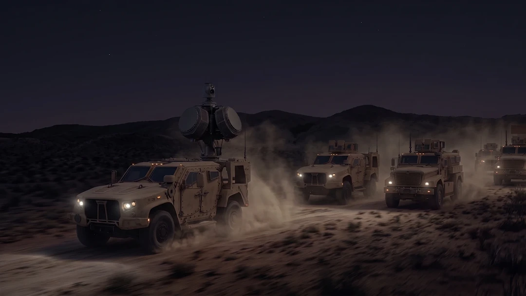
High-Precision Navigation at Scale for Counter Drone Technology
Unlock precision for your kinetic effector on-the-move. Discover how Advanced Navigation delivers the stabilization and supply chain speed needed for scalable counter drone defense.
18 May 2026
Go to Article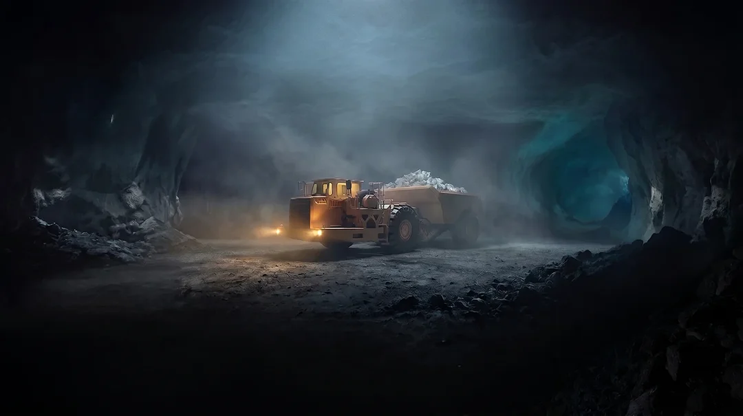
Navigating the Future of Mining Operations
Discover how to improve product quality in manufacturing through Advanced Navigation's rigorous supply chain and exhaustive validation.
5 May 2026
Go to Article