
Digitally Encoded Doppler Ranging and Velocity – A New Paradigm in Laser Based Measurement
Share:
Published on:
Advanced Navigation’s light detection altimetry and velocimetry (LiDAV) system sets a new benchmark for laser-based distance/range and velocity measurement. This patent pending technology delivers a navigational sensor capable of measuring distance and velocity with extreme accuracy and with less hardware than any other system with similar characteristics.
Table of Contents
- Technology Introduction
- Key Components of LiDAV
- Measuring Distance and Range Using Lasers
- Measuring Velocity Using Lasers
- Limitations of Pulse and Continuous Wave LiDAR
- Random Modulation Continuous Wave (RMCW) LiDAR Bridges the Gap Between Range and Precision of FMCW
- Putting LiDAV Into Use
Technology Introduction
Laser based photonics systems used to measure either or both velocity and range have traditionally been constrained by one or more critical factors that ultimately limit application of the technology. For example, a frequency modulated laser may produce excellent results within its applicable range, however, any data from the system outside of this range is ambiguous. In a practical sense, this may lead to multiple systems being required or additional sensors necessary for other ranges, for example.
LiDAV technology extends the capability of laser based simultaneous velocity and range measurement. The combination of specially developed components using digitally enhanced waveform interferometry and single frequency laser photonics to provide a combination of extended range and very high accuracy three-dimensional velocity measurement that significantly widens usage and value of the technology.
LiDAV measures velocity and position relative to the ground and objects by transmitting modulated laser beams toward the surface. Reflected laser light is collected using optical receiver sensors and, by measuring specific properties of the reflected beams, the range between the laser and illuminated surface and 3D velocity of the sensor can be calculated.
By using a phased array of lasers, the LiDAV system is not only capable of instantaneous velocity and range measurement, but can provide very precise vehicle motion information (roll, pitch, yaw)
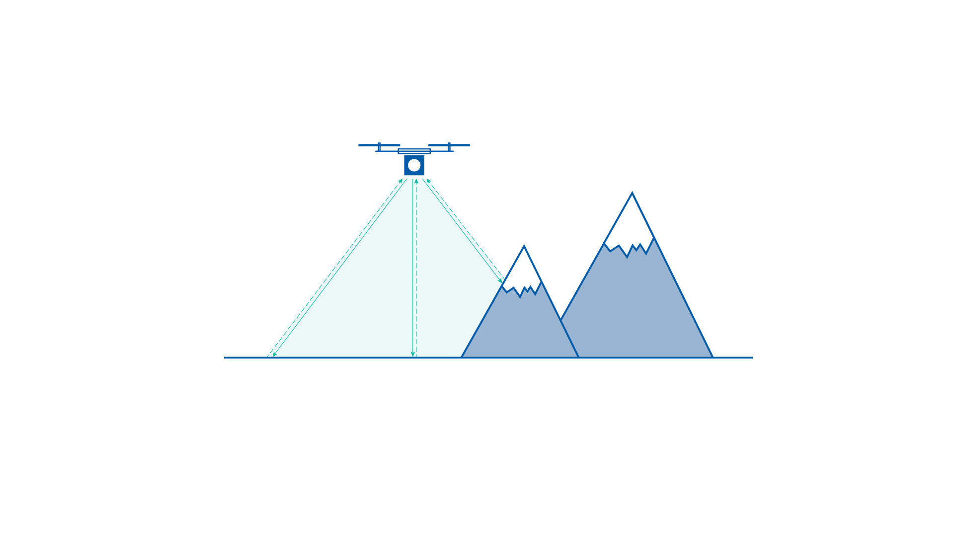
LiDAV sensors are suited to many applications, typically based on applicable range, including:
- Terrestrial vehicles – autonomous systems, GNSS-compromised scenarios, defense, underground mining, precision navigation
- Uncrewed aerial vehicles (UAV) – lightweight UAVs, drone, fixed wing glider, vertical takeoff and landing (VTOL) aircraft, helicopter, navigation, take-off, landing, situational awareness, GNSS-compromised scenarios, defense
- Fixed-wing aircraft – take-off, landing, situational awareness, hazard avoidance, navigation
- Spacecraft (particularly landing vehicles) – take-off, landing, situational awareness, hazard avoidance, navigation.

Vehicle applications suited to LiDAV – terrestrial vehicles, UAV, fixed-wing aircraft, spacecraft
Key Components of LiDAV
The primary components of the LiDAV sensor are the laser, modulator, telescope and optical receiver. The following image shows the basic components and operation of a LiDAV sensor.
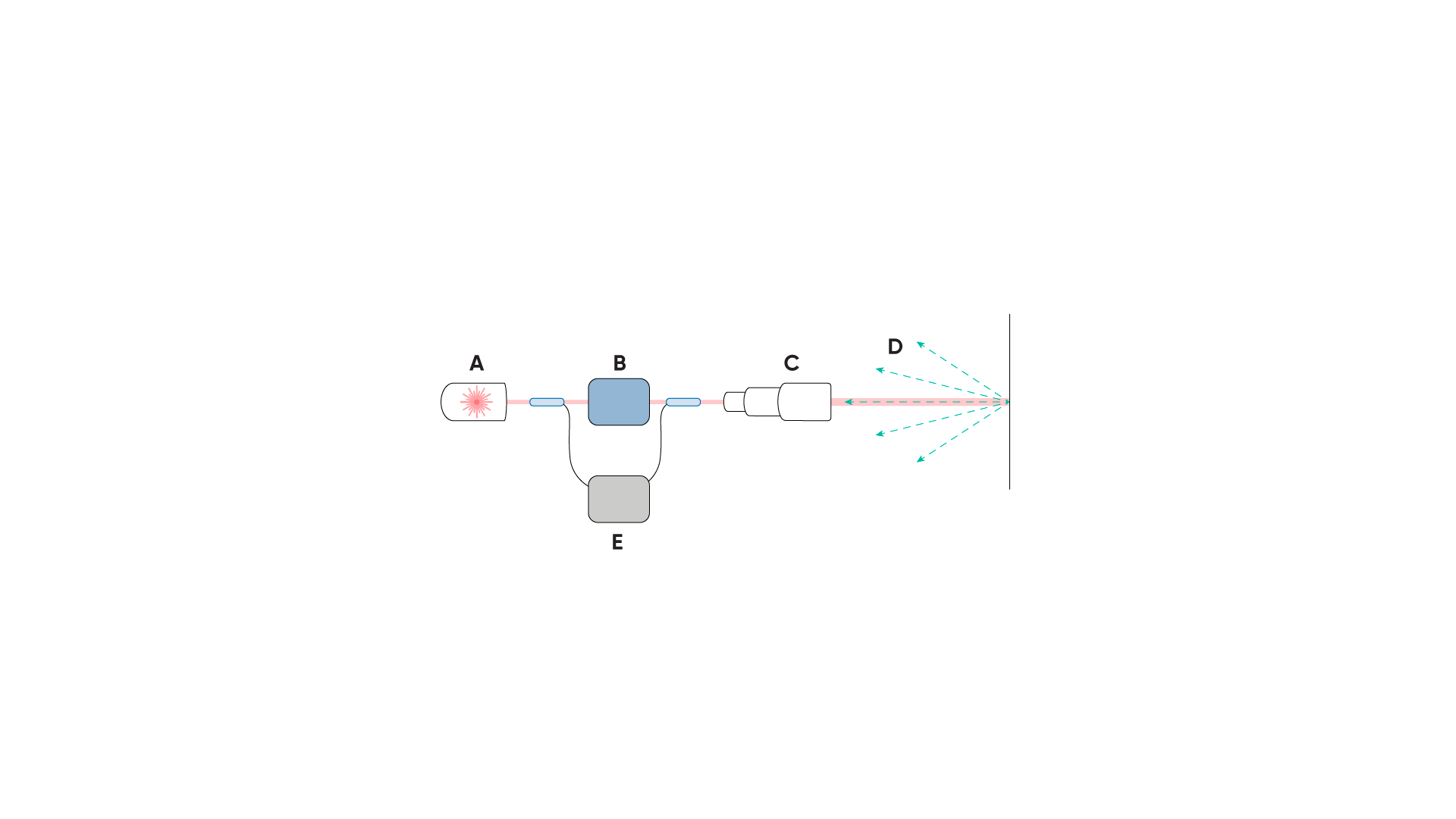
Output from the laser (A) is modified by the modulator (B) to provide a time varying attribute to the laser waveform before being emitted via the telescope (C). Reflected laser light (D) re-enters the sensor via the telescope and is sent to the optical receiver (E) for processing, resulting in output data
Laser
The term “laser” stands for light amplification by stimulated emission of radiation. The history behind laser technology began in the early 20th century, with initial theories for the probability of the absorption, spontaneous emission, and stimulated emission of electromagnetic radiation.
These concepts were encapsulated within “quantum radiation theory”, from which the quest to demonstrate stimulated emission began. This led to the development of a microwave amplifier in the 1950s, which itself inspired the idea of amplifying stimulated light radiation. In 1959, the term “LASER” was coined and by 1961, the first laser was built. Few inventions have had as significant an impact on modern society than the laser. From enabling high-speed internet to the detection of gravitational waves in 2015, lasers have truly shaped modern civilization. Since its first demonstration in 1960, laser technology and photonics have been the subject of relentless research and development
Laser light is created by applying electromagnetic radiation to stimulate electrons in a material that has specific optical properties (for example, crystal, or gas). This injection of energy can be absorbed and released by the electrons. Sometimes the energy is released in the form of a photon, which is light. This is stimulated emission. When you gaze at a fire, for example, the reddish glow of the embers are photons of red light being emitted by heat-excited atoms. In a laser, the idea is to excite the electrons and propagate this excited state to other electrons, and have the electrons emit photons that have identical characteristics.
The tremendous versatility of lasers enables them to be used in an extraordinary array of applications, many of which are seemingly miraculous, such as delicate surgical procedures, fibre-optic communications, gravitational wave detection, precision materials processing, and creating three-dimensional maps of the environment.
A laser is typically designed to release a specific wavelength – or “color” – of light using a particular optical material called a gain medium, amongst other things. The type of material determines the wavelength / color of the laser. For example, a Helium-Neon laser uses a mixture of gas as a gain medium to emit light at a specific 632.8 nm wavelength, which the human eye observes as red. Other lasers typically combine a laser diode with an optical cavity, which is essentially a pair of highly reflective mirrors that allow the light to bounce around inside. Under specific conditions, the light bouncing around inside the cavity resonates, improving the purity of the laser wavelength. The beam of laser light can be highly directional and tightly focused. This can be used to point the laser beam from the sensors in specific directions or onto specific surfaces.
This controlled method of stimulated photon emission is fundamental to producing a light that is said to be “coherent”. Coherence means the wavelength, direction, and polarization of the photons are the same to some extent. Critically to LiDAV, laser coherence enables the phase property of the laser light to be preserved as the laser propagates through the air / space. A coherent laser will produce a narrow range of wavelengths, whereas an incoherent laser will produce a broad range of wavelengths. Coherent lasers produce light over a very narrow band of the light spectrum, giving it a distinct color (if in the visible spectrum). A good example are the lasers used to transport data through optical fibers, which emit light at specific, narrow infrared wavelengths that cannot be seen by the human eye.
Specifically to LiDAV technology, the laser component is used to estimate the velocity and altitude of the sensor with respect to a nearby surface; for example, the ground. This is achieved by transmitting laser light from the sensor to a nearby surface, and then measuring properties of the laser light reflected off the surface.Because the laser is coherent, light reflected off the surface retains a phase relationship with the transmitted laser light. This means that at the optical sensor, the phase of the reflected laser can interact or interfere with the transmitted laser. The effect of phase interference enables the system to extract range and velocity information from the reflected beam.
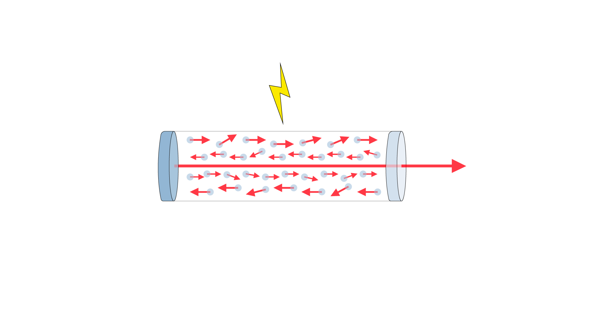
The example image depicts how laser light is propagated within an optical cavity through the injection of energy and reflection of light within the cavity. One side of the cavity features a partial reflector, through which the laser light outputs
Modulator
Modulators are used to control, or periodically vary, the phase, amplitude and frequency of the laser. The amplitude and / or phase is modulated using an electro-optic modulator. The frequency is modulated using an acousto-optic modulator. Modulators are used in modern telecommunications systems for encoding data / information onto laser light.
The modulator encodes a pseudo-random pattern in the form of an electrical signal into the phase of the light being sent out into the environment. This creates a modulation waveform within the laser light. The encoded pattern provides a time varying attribute into the light so that time-of-flight can be determined and that the modulated waveforms from the emitted and reflected laser light can be correlated and compared.
Random-modulation is used for several reasons. Firstly, it does not require direct modulation of the laser, which enables high precision and accuracy Doppler measurements. Secondly, random-modulation, paired with Advanced Navigation’s patented technology, preserves measurement precision and accuracy over extremely long distances by increasing the period of the modulation waveform.

Image on the left – Example image showing how laser light can carry a phase modulated waveform. The carrier waveform (A) is altered by the modulating waveform (B), resulting in the phase modulated waveform (C).
Image on the right – Example image showing how laser light can carry an amplitude modulated waveform. The carrier waveform (A) is altered by the modulating waveform (B), resulting in the amplitude modulated waveform (C).
Modulation also provides a method of resolving direction of travel. That is, being able to distinguish positive and negative velocities; for example, caused by moving forward and backward, up and down, left and right relative to the ground.
Fibre Collimator (“Telescope”)
The fibre collimator (commonly referred to as a “telescope”) is used to transmit the laser light into free space and to enable capturing some of the reflected light that scatters back from the illuminated surface (the telescope is a monostatic transceiver). The laser light is sent to the telescope via optical fibre, through the telescope optics and outward through the aperture. Reflected light must also pass through the aperture to be captured and processed by the optical receiver.
The telescopes are designed, configured, and optimized for different applications. Longer range applications typically require larger telescopes (that is, larger apertures) than shorter range applications. Telescope configuration is balanced with other design considerations including laser transmit power, optical receiver sensitivity, and constraints on signal processing. The telescopes are solid-state, which means no moving parts and higher reliability, and are fixed for focal length and aperture. The telescopes are also wavelength dependent because of anti-reflection coatings and the geometry of the telescope optics.
Optical Receiver
A coherent optical receiver is a device used in modern telecommunications systems for measuring data/information encoded onto laser light, including the amplitude or phase of the received laser beam. The optical receiver converts photons of captured light into electrons; that is, light into electrical current. The more efficient the receiver is at converting photons to electrons, the more sensitive it is, allowing it to detect weaker received optical power.
In the case of LiDAV, the optical receiver is also an interferometer. The interferometer overlays/combines/interferes the electric fields of the emitted and reflected light to detect and measure changes in phase of the modulated waveforms. From this, it is possible to extract velocity (from Doppler shift) and distance (from time-of-flight). If required, the optical receiver can apply gain (coherent amplification) to the received light to improve results.
All velocity and ranging information contained within the signal field is preserved in the interference waveform produced by the optical receiver. This enables analysis of the interference waveform to extract velocity (from Doppler) and distance.
Measuring Distance and Range Using Lasers
One of the earliest identified applications of lasers was to measure distance. In a simplistic sense, lasers can be used to measure distance by timing how long it takes for light to travel to and from some surface, often referred to as the round-trip time-of-flight (ToF) of the light. With this measurement, it is fairly straightforward to calculate the absolute distance (or range) between the laser source and the illuminated surface by multiplying the speed of light (300 million meters per second) by half the measured round-trip time-of-flight.
LiDAR (light detection and ranging), is the class of technologies that use light (typically lasers) to measure distance. The most common type of LiDAR uses optical pulses, where a short burst of light is transmitted towards a distant object and a photoreceiver is used to measure the light that scatters back towards the LiDAR sensor, as shown in the following image.
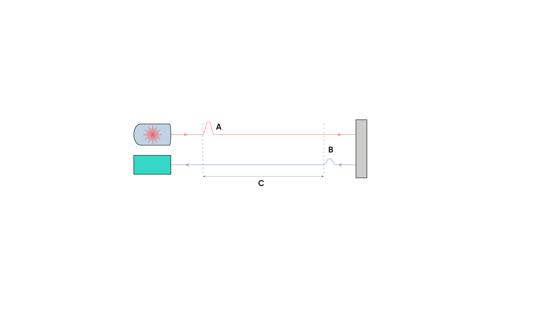
Example image of laser time-of-flight – the upper red line represents the emitted laser light, the lower blue line the reflected light. By using a time varying attribute, in this case a pulse in intensity (A), the time between the pulse being emitted and the reflected pulse (B) being detected can be calculated (C). Multiply 0.5 x ToF by the speed of light to determine range
LiDAR requires the laser to have some time varying attribute. For pulsed LiDAR, the time-varying attribute is laser intensity. It is also possible to vary other attributes of the light, for example, the laser frequency, phase, or polarization. Without a time-varying attribute, it is not possible to measure ToF.
For descriptions of some common LiDAR technology types, see “Limitations of pulse and continuous wave LiDAR“.
The maximum distance that a LiDAR sensor can measure depends largely on the amount of light that returns to the sensor, as well as the sensitivity of the receiver. In general, the more powerful the laser, the greater the distance it can measure. A typical application of LiDAR is topographical surveying, in which a LiDAR sensor mounted to an aircraft or UAV (uncrewed aerial vehicle) scans the laser over the ground as it is flying over to create a 3D map of the terrain, the data set of which is often referred to as a “point cloud”.
A point cloud is many thousands of individual laser distance measurements that are each geo-referenced to an absolute position on the Earth’s surface. This enables the creation of a three-dimensional digital twin of the area being surveyed.
Due to the fact that the scanning is being performed from a moving vehicle, to gain a high accuracy point cloud, the survey data must be referenced to not only a GNSS fix, but a high quality inertial navigation system (INS). The INS provides accurate data that describes movement of the vehicle during the survey that is critical for producing truly accurate point cloud data. Advanced Navigation designs and builds high accuracy inertial navigation systems that are extremely well suited to UAV surveying applications (read the NextCore cases study for more info). This system can rapidly provide very high levels of accuracy and detail, depending on point cloud density and equipment.
Measuring Velocity Using Lasers
There are several ways lasers can be used to measure velocity.
One approach is to subtract two consecutive measurements of distance to produce an estimate of change in range over some known time period. For example, a change in range of 100 mm over a period of 0.1 seconds would result in a velocity estimate of 1 m/s. Whilst conceptually simple, the precision and accuracy of this approach depends on several factors including range resolution (for example, 50 mm) and the frequency at which range measurements are produced (for example, 100 measurements per second). This technique also assumes that the same object/surface is illuminated between each measurement. If the sensor measures an object at close range followed by a different object at a longer distance (or vice versa), then the resulting velocity estimate will be inaccurate and would suggest an unrealistic acceleration. Note that it is not possible to directly measure velocity this way due to the relative nature of the components, however, velocity can be inferred very accurately because the laser wavelength and the speed of light are known.
A more direct way to measure velocity is to measure the Doppler frequency shift between the emitted and reflected light caused by the relative motion between the sensor and illuminated surface. This technique is often referred to as “Doppler LiDAR” or “coherent LiDAR”. A coherent single frequency laser is a controlled, pure light source, where the wavelength is known with absolute certainty. The smaller the wavelength, the higher the frequency, and the greater the precision of measurement becomes. Imagine two lasers; laser A has a 1064 nm wavelength and laser B has a 1550 nm wavelength. Laser A has an approximately 50 % shorter wavelength than laser B. In this example, laser A provides increased sensitivity of the observed frequency shift due to its smaller wavelength.
As a simple example of Doppler shift, imagine an ambulance with its siren on approaching from a distance, reaching your position, then continuing to move away from you. When the ambulance is far away, the siren sounds deeper and the tones longer because the frequency is lower; when the ambulance is close, the siren is much sharper and more assaulting to your ears due to the higher frequency. As the ambulance moves further away, the siren sounds deepens and lengthens.
Another important principle to Doppler LiDAR is that the velocity that it can measure is radial. This means that the relative planes of movement between the laser source and illuminated surface is very important. To put this into context:
- If the laser source is moving directly toward a surface, the reflected laser frequency increases – the laser is being “squeezed”.
- If the laser source is moving away from a surface, the reflected laser frequency decreases – the laser is being “extended”.
- If the laser source is moving in parallel to a surface, the reflected laser frequency is unchanged. This means that a radial velocity cannot be determined.
- If the laser source is moving through a different plane to the surface, the reflected laser frequency changes because of the change in radial velocity.
The means of attaining a velocity estimate is to use waveform interference.
Interferometry – Measuring Waveform Interference
Interferometry is basically the process of splitting a waveform, sending it on two different paths then recombining them and measuring any difference between the original and combined waveforms. A simple example of waveform interference can be observed when ocean waves coming from different directions “interfere” with one another. This may result in a larger wave if the peaks of the waves combine, or a diminished wave if the peaks of one wave meet the troughs of the other.
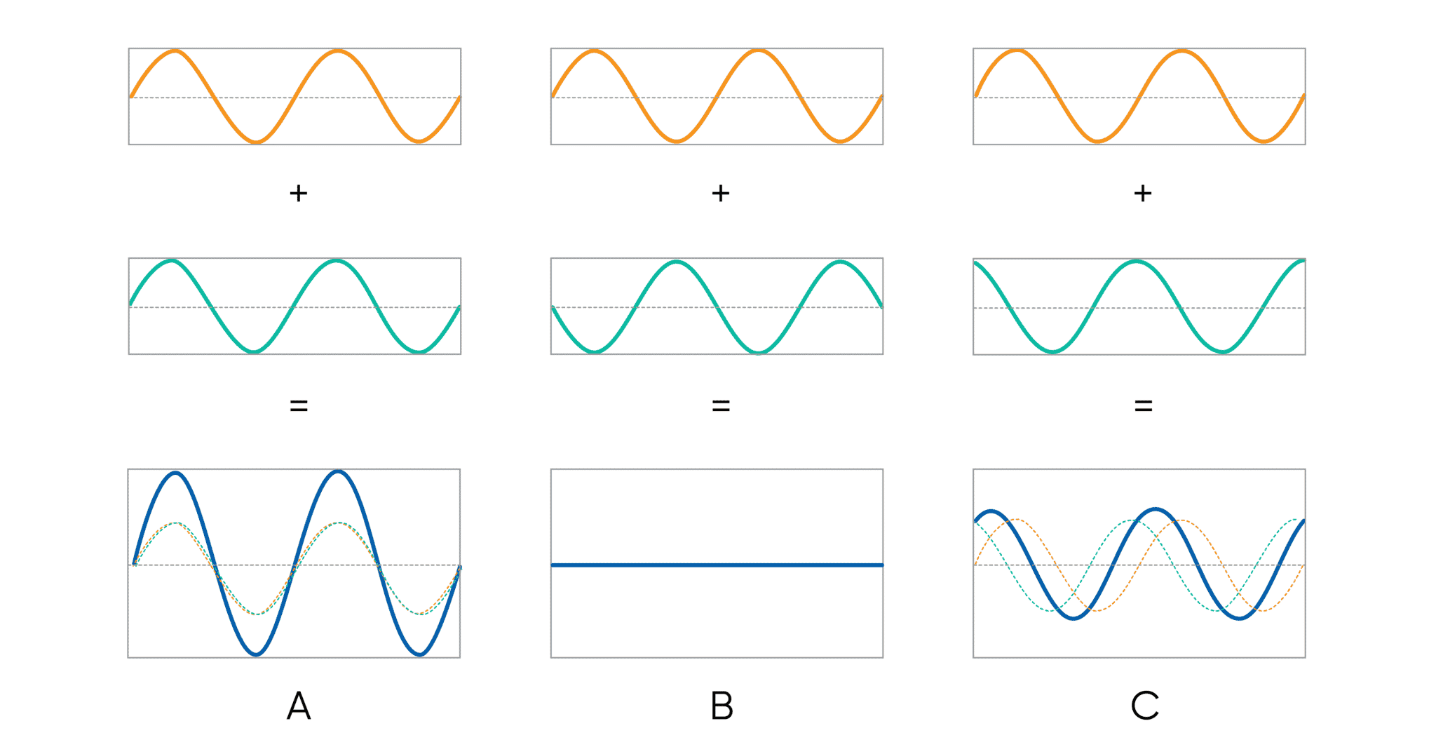
In the example image, the waveforms in (A) (orange and green) are in phase. When combined, the resulting waveform (blue) is larger – this is constructive interference. In (B) the waveforms are out of phase by 180° (inverse to one another). When combined, the resulting waveform is flat (zero amplitude) – this is destructive interference. In (C) the waveforms are out of phase by a small amount. When combined, the resulting waveform has a slightly larger amplitude than the original waveforms – this is constructive interference
As an example of interferometry using light as the waveform, the light is directed toward a mirror that is semi-coated in reflective material. This semi-reflective mirror allows half the light to pass through and half to be reflected, splitting the light. Secondary mirrors will redirect the light so that it recombines.
If the position or angle of one of the mirrors changes due to some external force, say, gravity by even a tiny amount, the waveform of the deflected light will shift in relation to the reference light waveform (phase shift). When the light waveforms are recombined, there will be measurable differences in the waveform fringes (the edges) where parts that were dark now have light and vice-versa. This is an extremely accurate means of measurement due to the very short wavelength of light.
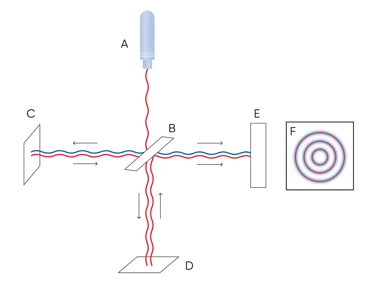
In a basic laser interferometer, laser light (A) is directed towards a semi-reflective mirror (B). The light reflected off the mirror is transmitted to the environment (C) The light scattering back from the environment may have Doppler shift due to difference in relative velocity. The light transmitted through the mirror is reflected off a mirror (D). The reflected laser light from C and D are combined on the beam-splitter (B), where they interfere. The detector (E) measures beams and converts it into an electronic signal. Relative velocity is manifested as a beat-note signal which can be measured
In a LiDAR application, the reflected waveform is combined with a local copy of the waveform to measure the result of any interference. Any differences are then used to calculate an inferred velocity based on the optical beat note between the two lasers.
Limitations of Pulse and Continuous Wave LiDAR
Up to this point, we have discussed how a laser can be used to measure absolute distance and to infer radial velocity. For absolute distance and ranging measurements, an essential requirement is an attribute that is a function of time, to attain time of flight (ToF). Every form of LiDAR must measure how long it takes for the photons to go from the laser to the object and back again. This is a technical challenge to achieve and process because light travels at a speed of 300 million meters per second.
Pulse LiDAR
This technique uses individual laser pulse emissions and waits for the reflected laser ToF to calculate distance. This technique does not provide a continuous waveform that would enable Doppler shift measurement, so cannot be used for velocity. A main limitation with pulse LiDAR is that the system must wait for the pulse to come back before sending another pulse – if further pulses are sent while waiting for the previous reflection, it quickly becomes possible to lose track of which reflection is associated with which pulse.

Simplified animation of FMCW LiDAR – Changes in range between the emitted light and illuminated surface is detected as a Doppler shift in the reflected light. The image shows how the reflected light frequency varies (compresses and extends) as range changes
A performance limitation with this system, however, is a dependency on how fast the change in frequency is. That is, the faster or slower the chirp, the shorter or longer the time window for measurement becomes and this affects the available measurement range and precision. For example, a 10 nanosecond (10 billionths of a second) chirp means that the effective range is limited to the speed of light distance over 10 nanoseconds, which equates to incredible precision at a range of 3 m. Similarly, if you want a 300 m range, the chirp length becomes a microsecond. This means that there is a reduction in precision of the sensor. The longer the chirp time, the more the precision reduces. Taking this a step further, if you want to measure something at 1000 m or 10000 m away, you have to trade off the resolution of measurement to achieve measurements over those ranges.
Frequency Modulated Continuous Wave (FMCW) LiDAR
Another technique used to provide a time varying attribute is to use a continuous beam of laser light and modulate the frequency at regular intervals, known as sweeping the frequency. If you were to think of this in an audible sense, the laser “chirps”. This is a more efficient method than pulse LiDAR as the sensitivity is much higher. A major advantage of FMCW over pulse LiDAR is that the repeated waveform pattern will present as a Doppler frequency shift if there is a radial velocity change. This enables radial velocity and distance to be resolved simultaneously, making it in its own right a remarkable technology.
Simplified animation of FMCW LiDAR – Changes in range between the emitted light and illuminated surface is detected as a Doppler shift in the reflected light. The image shows how the reflected light frequency varies (compresses and extends) as range changes
A performance limitation with this system, however, is a dependency on how fast the change in frequency is. That is, the faster or slower the chirp, the shorter or longer the time window for measurement becomes and this affects the available measurement range and precision. For example, a 10 nanosecond (10 billionths of a second) chirp means that the effective range is limited to the speed of light distance over 10 nanoseconds, which equates to incredible precision at a range of 3 m. Similarly, if you want a 300 m range, the chirp length becomes a microsecond. This means that there is a reduction in precision of the sensor. The longer the chirp time, the more the precision reduces. Taking this a step further, if you want to measure something at 1000 m or 10000 m away, you have to trade off the resolution of measurement to achieve measurements over those ranges.
Random Modulation Continuous Wave (RMCW) LiDAR Bridges the Gap Between Range and Precision of FMCW
The Advanced Navigation system uses a patented technique called random modulation continuous wave (RMCW) LiDAR. This is new technology born of initial research in gravitational wave detection and space instrumentation. This technique not only resolves existing limitations of FMCW LiDAR, but actually introduces new possibilities for laser based data acquisition.
The fundamental mission of RMCW LiDAR is to provide an unvarying precision for distance and radial velocity measurement that is unaffected by range. Of course, there are constraints to all forms of technology and, although it may not be always possible to replicate the absolute precision of FMCW at very short ranges, the RMCW technique provides excellent and reliable precision up to ranges, at this point, of 10000 m.
The methodology behind this technique is to introduce a time varying attribute, however, without affecting the laser frequency waveform. Referring back to FMCW, the waveform itself is the means of providing this variance to determine ToF. To not change the waveform and keep it absolutely “pure” requires something else to effectively be carried by the laser waveform. To effect this, a pseudo-random binary sequence is encoded into the phase of the laser to provide the time varying attribute.
The idea of a binary encoded laser was first developed in 1983, using an incoherent (variable waveform) laser. This was a significant development in LiDAR technology, however, due to the waveform incoherence it was incapable of velocity measurement.
Breakthrough Technology That synthesizes Binary Encoded Coherent Laser – LiDAV
In 2019 the Advanced Navigation photonics team pioneered a method of binary encoding coherent laser to provide simultaneous ranging and velocity data – light detection, altimetry and velocimetry (LiDAV). The pseudo-random binary encoding is implemented using a similar concept to how the telecommunications industry is able to distribute and connect millions of simultaneous telephone calls, data feeds and media streams through basically limited channels without interference or buffering. This is accomplished by uniquely encoding each individual connection, similar to a fingerprint, in order to split and restitch them – this is the concept of multiplexing. Similarly, adopting some of the techniques and hardware developed by the telecoms industry provides a robust and well established pathway to use in developing LiDAV technology.
We know how velocity is estimated using Doppler shift measurement. Any Doppler shift is readily detected through waveform interference of the emitted and reflected light. Therefore, velocity estimation is unaffected by binary encoding of the laser. The thing to recognize about the Doppler effect is that sensitivity is proportional to frequency. So, the higher the frequency, the greater the sensitivity. The relationship between frequency and wavelength is described as optical frequency = speed of light / wavelength. In this case:
f = 3 x 10⁸ m/s / 1550 x 10-9 m = 193.5 THz
Using Ku band radar as a comparison, the radar frequency is ~20 GHz (200 x 108); for LiDAV, the laser light frequency is ~193.5 THz (193.5 x 10¹²). Noting that sensitivity is proportional to frequency, LiDAV is ~10000 times more sensitive.
“Our technology is more accurate in terms of precision and instantaneous velocity estimation with big gains in reaction time. For example, we can instantly detect deceleration or acceleration in the order of micrometers per second.”
Dr. Lyle Roberts, Advanced Navigation Photonics Team Lead
Distance is measured by correlating the reflected binary sequence with a local copy of the sequence. Correlation is the degree to which two variables move in coordination with one another and provides the time varying attribute. In this case, the binary code sequences of the local and reflected waveforms are superimposed to determine any positional difference between them. The correlator calculates how much shift is required to align the code sequences and using this information and wavelength, ToF is determined.
If you recall the chirp length being a somewhat limiting factor in FMCW LiDAR, this is overcome in the LiDAV system because it supports optimizing the length of the pseudo-random binary code sequence based on factors such as current distance and optimization of precision. It is through this autonomous dynamic optimization that LiDAV is able to consistently maintain precision over its entire detection range. This is a fundamental difference between LiDAV and other laser ranging and velocity measurement technologies.
Historically, single frequency lasers have been prohibitively expensive for widespread adoption because attaining a pure single frequency requires photons at a very specific frequency, and this means using a specially designed cavity. Using a telecoms wavelength (1550 nm) as a design platform is a sensible approach as it utilizes existing research and development and proven technology. The 1550 nm wavelength provides several advantages, including that it enables the laser light to propagate through air with minimal loss and also demonstrates minimal loss when traveling through optical fibre. There is also an abundance of reliable components and functionality available for use in the 1550 nm wavelength, which combined make designing and building equipment more efficient and cost effective.
Defining New Levels of Reliability and Resilience
Reliability of sensor and navigation technology is critical to any autonomous system. Currently technologies such as radar, LiDAR and camera based visual systems often present inherent limitations. For example, cameras being unable to operate reliably in low or no-light conditions. Similarly, environmental particulates such as dust or the substrate itself can render LiDAR and radar to be less reliable
LiDAV provides markedly increased availability and reliability over other technologies and also delivers extended useful data. LiDAV photonics technology enables not only very accurate, instantaneous motion information but is totally immune to interference at the physical level (light availability, dust and surface material) and at the software level (radiation induced data corruption).
The Anatomy of 3D Orientation and Laser Analysis
A single laser is fine for a single range measurement, however, this severely impacts its usefulness in a practical sense. LiDAV uses multiple lasers that are accurately oriented to provide a multi-point sensing system. Think of the laser telescopes being projected outward in a tripod-like formation. In the same way that the legs of a tripod can be individually adjusted to set-up a camera to be horizontal even when the ground is uneven, the readings from each laser telescope provide information that is used to determine orientation of the system with regard to a surface. Not only that, but information about the surface topography can also be deduced from the data
Due to the very high sensitivity and precision for ranging and radial velocity acquisition, this system provides data for rotational movement around the X, Y, and Z axes (roll, pitch and yaw) and linear movement along each axis (forward/backward, left/right, up/down).
The reflected light can be analyzed to reveal additional information. For example, analyzing the polarization can provide information about the nature of the illuminated surface, such as water or ice or metal or rock or dust and so on. Using AI enhanced analytics and learning capability greatly increases the overall potential of the system to supplant other sensors, such as camera systems to photograph a surface and use photo-analysis to determine the substrate. This also means that additional dependencies, such as light for photographic exposure, are eliminated.
Applying Artificial Intelligence to Learn and Correct
Advanced Navigation is renowned for technical innovation and new thinking to overcome challenges and advance science and technology. A lynchpin to this is pioneering AI neural networks into inertial navigation systems. The advantages of using AI and its implementation over traditional mathematical filtering are faster sensor updates and processing, better error tracking and resulting higher accuracy. Being able to use past data during processing enables the system to learn and apply self correction.
For the LiDAV system, AI based learning capabilities are designed into the sensor processing platform. Again, this is used for system learning and improved accuracy, corrections and estimation and for the new levels of laser analytics.
Using FPGA for Large Scale Data Processing
As you can imagine, the amount of data that can be generated by this multi-purpose laser technology is huge – approximately 80 Gb per second or more. This volume of data processing requires a different model for data processing than a traditional CPU based format. Using field programmable gate array (FPGA) processing increases efficiency by spreading the compute load over what are effectively a very large number of task delineated logic cells.
To explain, a single chef in a kitchen can perform a few tasks at once, however, each meal is basically created one at a time. Now, if there were multiple chefs, each doing a specific task, many more meals could be created simultaneously. FPGA elements are not as fast as a CPU for raw processing power, however, because the tasks are being parallelized over basically millions of logic gates (AND, OR, NOT et cetera), the volume of data being processed is much greater.
FPGA elements can be defined to perform specific tasks; for example, calculations. The FPGA itself is capable of formulating the most efficient use and linking of logic gates to most effectively form a software based “circuit board” to perform this single task. Several Advanced Navigation products, including LiDAV, Boreas DFOG and Hydrus AUV use FPGA technology to handle the very high levels of data these devices produce. Timely handling of data is essential to maintaining high performance, ultra-responsive sensors and integrated systems.
Another huge advantage that FPGA has over fixed circuitry is that it can be reprogrammed in the field. This is a very elegant upgrade / support function that overcomes previous limitations in having to, for example, release software or firmware or indeed, redesign circuit boards and retrofit them.
Putting LiDAV Into Use
LiDAV offers a game changing solution to ranging and velocity measurement for various vehicles. Vertical take-off and landing (VTOL) aircraft and ground vehicles immediately come to mind and, with the advent of autonomous vehicles and suitable guidance systems, the level of precision and versatility available through LiDAV will accelerate rollout of this technology.
The precision that the system offers in terms of orientation data that it can provide makes it extremely exciting as a navigational aid. Fusing LiDAV to an inertial navigation system (INS) provides a huge boost in INS dead-reckoning performance. This will render next-level autonomous navigation performance and will provide new standards for navigation in general and particularly in applications that are GNSS denied or require resilience against degraded or spoofed satellite signals.
LiDAV does not depend upon any external signals or systems, making it virtually impossible to jam. In addition to providing advantages in GNSS-denied environments, LiDAV also provides benefits in applications where precise, real-time knowledge of a vehicle’s ground-relative altitude and orientation is critical.
LiDAV in Space
Innovative US based space vehicle design house and builder, Intuitive Machines, has selected Advanced Navigation LiDAV technology as equipment on their autonomous lunar landers and exploratory rovers and drones. These vehicles form part of a fleet that are contracted to the US National Aeronautics and Space Agency (NASA) intention for extended lunar exploration through the Artemis program. Part of Artemis is the Commercial Lunar Payload Services (CLPS) initiative, which is for delivering scientific and technology payloads to the lunar surface via the Intuitive Machines lunar landers. Read our case study on this exciting partnership “Intuitive Machines Looks To Advanced Navigation Laser Velocity And Ranging Technology For Autonomous Commercial Lunar Landings“.
Recent Tech Articles
How Improved Positional Accuracy Can Transform Mining Excavation
Explore the new standard in absolute positioning for GNSS-denied environments. See how the Chimera Land LVS and INS pairing anchors real machine motion.
15 June 2026
Go to Article
High-Precision Navigation at Scale for Counter Drone Technology
Unlock precision for your kinetic effector on-the-move. Discover how Advanced Navigation delivers the stabilization and supply chain speed needed for scalable counter drone defense.
18 May 2026
Go to Article
Navigating the Future of Mining Operations
Discover how to improve product quality in manufacturing through Advanced Navigation's rigorous supply chain and exhaustive validation.
5 May 2026
Go to Article