Tech Article

Published on:
Authored by: Patrick Wiltshire, Dr. David McManus, Dr. James Spollard, Mark Gibson, Matthew Suntup, Tim Laws, and Dr. Lyle Roberts
Advanced Navigation’s Boreas D90 Inertial Navigation System (INS) and Laser Velocity Sensor (LVS) were successfully demonstrated at Europe’s deepest underground mine in Pyhäjärvi, Finland as part of BHP’s Deep Mining Challenge. The Hybrid Navigation System demonstrated long-range, infrastructure-free, real-time navigation in a deep, GPS-denied environment. A one-time surface calibration using RTK GNSS aligned the LVS and INS frames on a vehicle of opportunity, after which all trials were unaided within the underground environment.
Across multiple tests, including a 22.920 km run at ~1400 m depth, the hybrid system achieved well below the goal of a sub-0.1% error rate over the distance traveled. In one trial, a final error of 0.55 ±0.09 meters over 6008 meters (0.0091%) was achieved, exceeding the benchmark by more than an order of magnitude. A fully underground initialisation and traverse resulted in 1.03 ±0.02 meter error over 1067 meters (0.093%). All tests were performed without prior knowledge of the mine layout, or the use of any existing infrastructure. Position accuracy was maintained across all axes, with consistent performance across depth, loop closure, and initialization scenarios.
Reliable navigation and positioning in underground mining environments remains a significant challenge due to the absence of Global Navigation Satellite Systems (GNSS). Without GNSS or widespread fixed-infrastructure, underground operations lack a dependable, vehicle-mounted positioning reference, making overall fleet management, material tracking, surveying, and vehicle guidance inherently more complex and resource-intensive.
Alternative positioning technologies have been developed, including waypoint-based systems using ultra-wideband beacons, WiFi, and 5G repeaters. Other techniques rely on perception-based methods, including SLAM, using cameras and LiDAR. However, these approaches are either heavily dependent on external infrastructure, or struggle with the harsh, variable conditions found underground. Repetitive features may confuse map-matching algorithms, beacons may fail due to being damaged by vehicles, or provide intermittent updates due to line of sight limitations and multi-path interference. Fixed infrastructure is often more costly to install and maintain than first estimated, with more than 75% of the installation time being spent on cabling alone[1]. Furthermore, fixed infrastructure does not exist in development areas, often requiring the involvement of surveyors, who are already in high-demand.
These are not minor technical constraints – they are major operational bottlenecks. Inaccurate or unreliable positioning has the potential to degrade the cycle time efficiency of load and haul operations, can ambiguate material and vehicle movement, resulting in lower yield, reduces safety, and limits advances in pro-active collision avoidance technologies. Critically, it slows the further adoption of tele-remote operation – a necessity for keeping people out of harm’s way (with the long-term goal of zero-entry mining).
In contrast, accurate and resilient vehicle-based positioning greatly improves real-time vehicle tracking, which in turn, can improve dispatching, as well as material handling and reconciliation. It also opens the door to enabling operation in development areas, with a logical flow onto more advanced, pro-active collision avoidance systems.
While no single technology will solve every challenge, a vehicle-based, inertial-centered architecture, integrating a range of complementary technologies, is a necessary foundation for the long-term goals of the mining sector: efficient ore extraction at depths which are hostile for human activity, via resilient, autonomous and tele-remote operations.
Advanced Navigation’s Laser Velocity Sensor (LVS), paired with the Boreas D90 fiber-optic gyroscope-based Inertial Navigation System (INS), offers a breakthrough: a vehicle-based navigation capability tailored for underground mining. This sensor pairing, referred to as Hybrid Navigation System was demonstrated at the Callio Mine in Pyhäjärvi, Finland, achieving repeatable accuracy better than 0.1% of distance traveled across five independent runs – all without external aiding or fixed infrastructure. While not a complete replacement for infrastructure-based systems, this technology significantly reduces reliance on them, enabling resilient, high-precision navigation in previously inaccessible or unmapped areas. This performance represents a step change toward enabling real-time tracking, optimized haulage, predictable collision avoidance, and scalable autonomous mining.
“At Normet, we specialise in advanced solutions for underground mining and tunnelling, so we know firsthand how difficult accurate and reliable navigation can be in these environments. Seeing Advanced Navigation’s Hybrid Navigation System deliver consistent positioning with minimal infrastructure deep within the Pyhäsalmi Mine was remarkable. It’s a powerful step forward for automation and safety in the underground space.”
Olli Mylläri, Vice President Technology at Normet
As we look further into the future, mining operations must shift to deeper, more complex environments that only become more hostile as they develop further into the orebody. Robust, vehicle-based positioning systems, operating with little to no external reference, will become a fundamental requirement for accessing and extracting critical resources moving forward. Unlike surface operations, ubiquitous technologies like GNSS are unavailable, and when “GPS repeater” style implementations have been tried, they were unusable due to signal obstruction and multipath, necessitating alternative navigation technologies. These can be broadly categorised into two groups: infrastructure-based and vehicle-based systems.
These systems rely on fixed transmitters installed throughout the mine, enabling vehicles equipped with receivers to determine their location based on signal characteristics. Key technologies include WiFi, 5G, Ultra-Wideband (UWB), and Bluetooth Low Energy (BLE). To function correctly, the absolute positions of these fixed transmitters (also called anchor nodes) must be known with high precision. This requires careful surveying during installation using traditional geodetic instruments such as total stations. Each anchor’s position must be tied into the mine’s coordinate system, often a local or global reference frame through line-of-sight measurements and network adjustments[2]. In dynamic or expanding mine environments, the infrastructure must be regularly updated and re-surveyed, making maintenance a continuous challenge[3].
WiFi positioning systems can leverage existing wireless LAN infrastructure, reducing additional deployment costs[2]. Positioning is typically achieved through techniques like fingerprinting or trilateration (TRI), which rely on Received Signal Strength Indicator (RSSI) values between devices and access points with accuracy generally ranging from 3–15 meters[4]. However, the need for a dense network of access points and the complexity of constructing fingerprint databases introduce installation complexity. Environmental factors like multipath propagation, non-line-of-sight, and electromagnetic interference also limit accuracy[2].
UWB promises high-precision positioning, often at centimeter-level accuracy using time-of-arrival (ToA) techniques. However, UWB systems require careful installation and calibration using precise surveying methods. Performance can also be affected by multipath effects, signal attenuation, and synchronization errors. Thus, typical real-world error is often an order of magnitude or greater than the technology’s ultimate potential. Notably, sub-meter accuracy in UWB deployments has been demonstrated at the Reiche Zeche mine in Germany[5], highlighting the impact of tunnel geometry on dilution of precision (DOP), while also underscoring the importance of strategic anchor placement in underground settings.
Bluetooth Low Energy (BLE) offers a low-cost, low-power solution, with typical communication ranges of around 10m[6]. BLE systems typically rely on RSSI-based trilateration or fingerprinting, with 1-5 meter positioning accuracy[2]. Their practical use has been demonstrated in mines for vehicle tracking and route optimization[7]. However, BLE systems require a high density of beacons to maintain acceptable accuracy and coverage in the constrained geometries of underground tunnels. As with other RF systems, performance suffers from signal attenuation, occlusions, and interference.
Total Stations deliver millimeter-level accuracy using optical measurements to fixed prisms[8]. They require direct line-of-sight and are typically tripod-mounted in surveyed locations. Though highly precise in static measurements of a single asset, their use underground for wider fleet management is limited by line-of-sight requirements, the need for manual setup, and often struggle to provide reliable performance while tracking moving vehicles due to vibration and environmental effects.
While many underground positioning systems rely on fixed infrastructure, an increasingly viable alternative is infrastructure-free technology. These technologies enable navigation using only onboard sensors without the exclusive need for pre-installed beacons or access points. These systems-such as Inertial Navigation Systems (INS), Visual Simultaneous Localisation and Mapping (Visual SLAM), and Light Detection and Ranging (LiDAR) SLAM-compute position by integrating internal sensor data or constructing and position matching real-time maps of the surrounding environment. Their independence from fixed infrastructure enables greater flexibility in dynamic environments, particularly at advancing headings, though challenges remain around drift, processing load, and robustness to harsh conditions.
INS rely on Inertial Measurement Units (IMUs), which use accelerometers and gyroscopes to measure acceleration and angular velocity. By integrating these signals over time, the system continuously estimates position, velocity, and orientation. As a self-contained solution, INS requires no external infrastructure. Installation simply involves mounting the INS on a vehicle, but accurate initialisation – typically using surface GNSS or local underground references – is critical to reduce early error. Since INS’ don’t directly measure position, its estimates inevitably diverge from the true position over time, with errors growing quadratically. When aided by external sensors, such as velocity references like a wheel-speed encoder, this error growth can be constrained to a linear rate.
Visual SLAM estimates a vehicle’s motion while building a 3D map using camera imagery. It requires minimal physical installation – usually just mounting one or more cameras and an INS – but relies heavily on the visual quality of the environment. Algorithms extract and track features across images to estimate pose and construct maps in real time[9]. Visual SLAM has demonstrated sub-meter accuracy in underground environments, with results such as 1.2 m average error from the LookUP system[10]. However, underground mines pose serious challenges: poor lighting, dust, low-texture surfaces, and repetitive geometries can impair feature detection and matching[11]. Additionally, Visual SLAM systems are computationally intensive, whilst promising, their deployment is typically limited to specialized survey vehicles in controlled conditions.
LiDAR SLAM uses laser scanning to generate high-resolution 3D point clouds of the environment, which are then used to estimate movement and build spatial maps. Like Visual SLAM, it is infrastructure-free, requiring only that LiDAR sensors be mounted on mobile platforms. Its key advantage is robustness to lighting conditions, making it well-suited for dark or variable environments. LiDAR SLAM systems are capable of high accuracies, with average position error of 0.13m utilizing computationally intensive post processing of collected data sets[12]. However, challenges include vulnerability to dust interference, high initial cost of 3D LiDAR sensors, and complex data processing requirements for real-time operation[2]. The system’s performance is also affected by non-rigid platform motion, initial pose uncertainty, and difficulty resolving position in geometrically ambiguous areas.
Autonomous mining underground requires reliable and accurate positioning that minimizes reliance on extensive fixed external infrastructure. Advanced Navigation addresses this need by combining their newly developed Laser Velocity Sensor with their existing Boreas D90 INS.
The Boreas D90 is a high-performance INS that uses Fiber Optic Gyroscope (FOG) technology and accurate accelerometers to continuously estimate position, velocity, and orientation. It features highly accurate gyrocompassing, determining its heading relative to true North without GNSS or magnetic signals.
The LVS measures a vehicle’s ground-relative 3D velocity with extraordinary accuracy by exploiting the relativistic Doppler effect. This robust sensor performs well in challenging mine environments, including dust and darkness, given a clear line of sight to a surface.
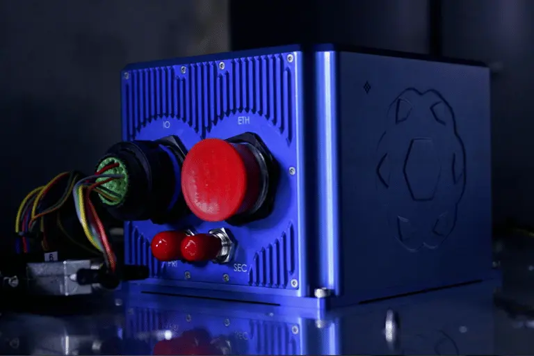
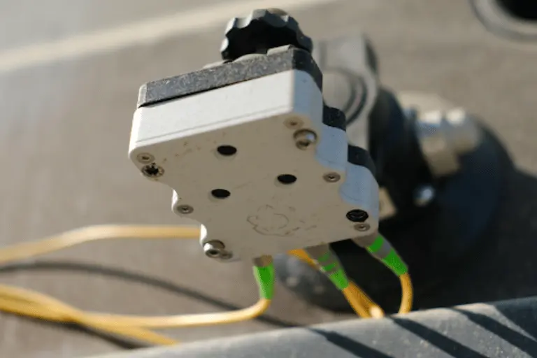
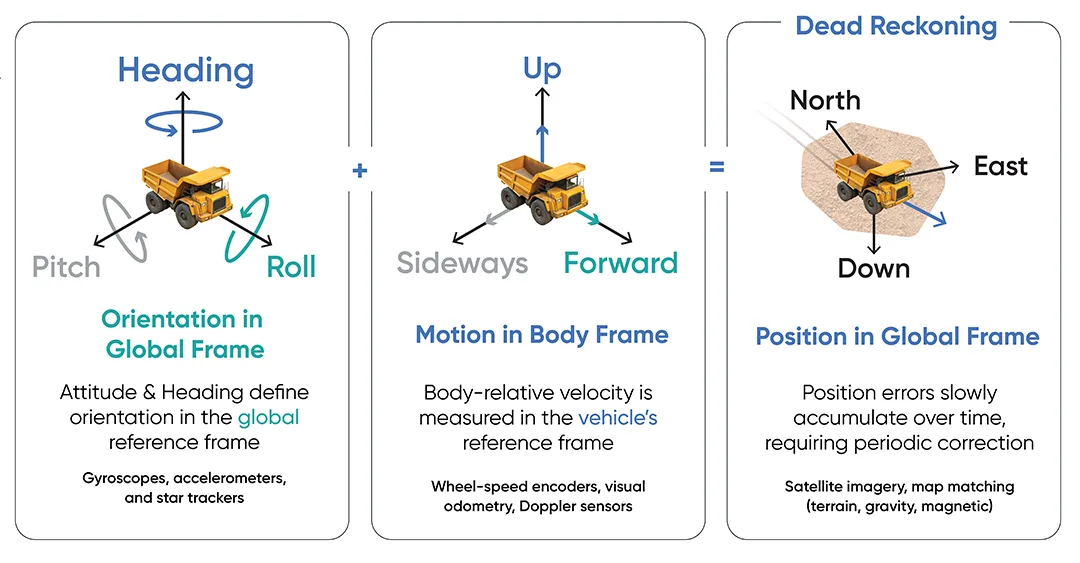
Figure 1: An INS estimates how the vehicle is oriented in the global frame (heading, roll and pitch), while LVS measures relative motion in the body-frame of the vehicle. This information can be combined to estimate the vehicle’s position in the global frame.
The strength of this technology lies in the seamless integration of the Boreas D90 INS with the LVS. While an INS drifts over time without external corrections , the LVS anchors the solution by providing continuous, highly accurate velocity updates, acting as a critical aiding source. This sensor fusion dynamically combines data, filtering noise and errors to maintain a precise and stable navigation solution over extended distances and time. This approach significantly reduces the need for extensive fixed external infrastructure, offering scalability, cost-effectiveness, and enhanced resilience for underground navigation.
For more information on the Laser Velocity Sensor, refer to this technical article.
Testing was conducted at the Pyhäsalmi Mine located in Pyhäjärvi, Finland. The site is home to Europe’s deepest base metal mine, with the lowest level of the mine at 1430 m below surface. While its active mining operations have ceased, the site is now managed by the Callio project, transforming it into a unique, multidisciplinary underground research and development environment.
Access to the mine was organized as part of Advanced Navigation’s involvement with the Deep Mining Open Call as part of BHP’s Think and Act Differently (TAD) program. The call aims to identify innovators with capability that could be applied to deep underground mining. The focus was on addressing challenges such as high temperature, high rock stress, and hypersaline conditions in deep mining environments. Its significant depth, realistic mine conditions, and inactive status make it an exceptionally valuable setting for testing these technologies.
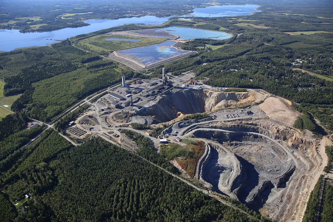
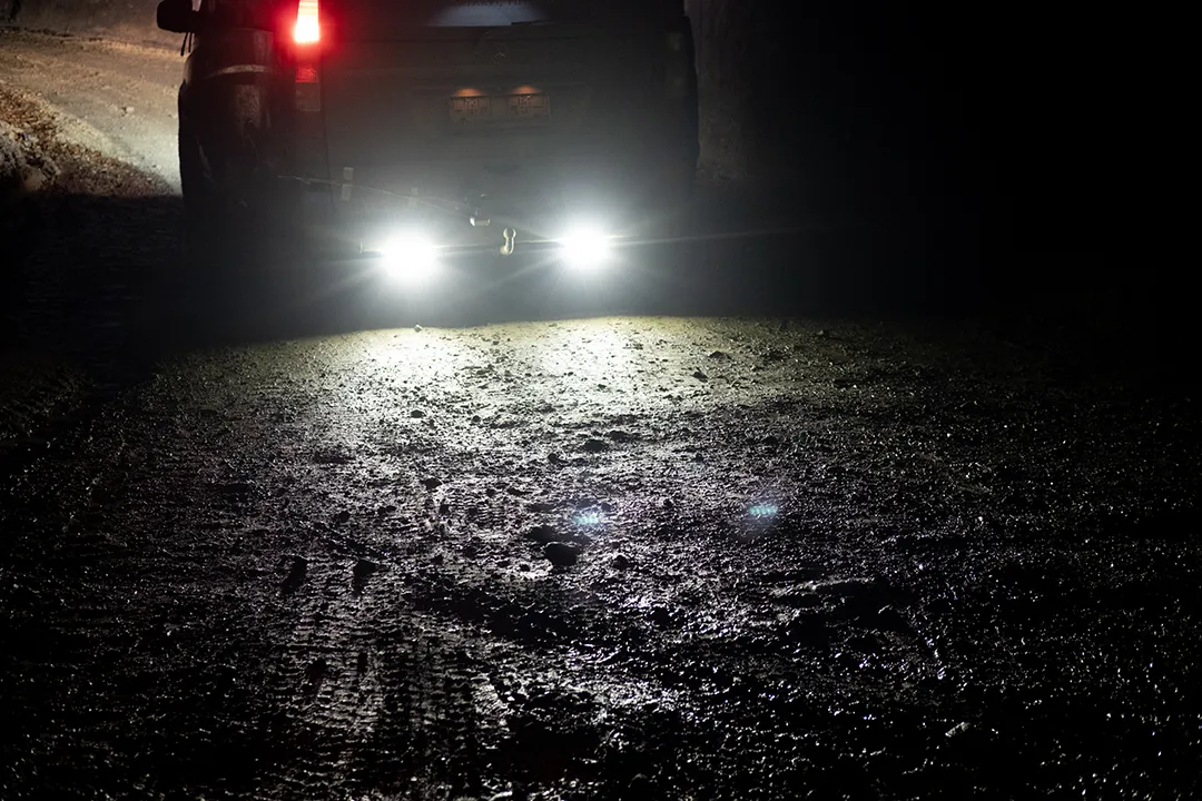
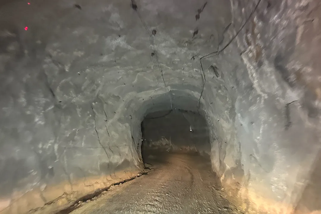
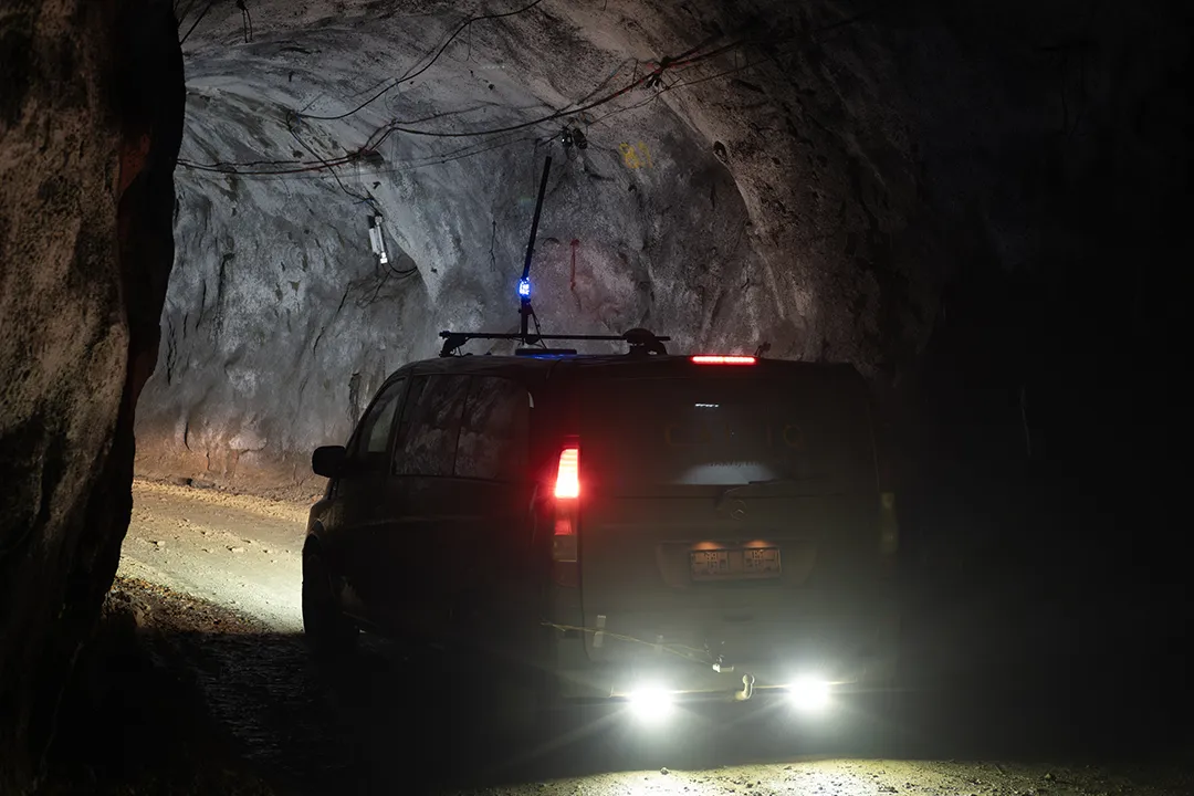
Figure 2: Aerial view of the Pyhäsalmi Mine in Finland, B. Typical image of sub-surface road conditions with loose gravel and dampness, C. Typical image of tunnel decline, D. Test vehicle traversing tunnel decline.
The mine features a series of tunnel declines that descend to different service, storage and maintenance halls that exist along the access tunnel. The main tunnel is ~11 km in length with an average gradient of 13%. Testing was primarily conducted within the main tunnel segment.
The LVS sensor features two components: an external, passive optical head, and an active sensor body. The optical head is primarily responsible for rigidly holding the alignment between the three telescopes. The sensor body houses the active photonics system, laser, and processing system.
The optical head must be mounted such that there is a clear line of sight between each telescope and the terrain. For this test it was chosen to mount the optical head via suction cup to the back of the test vehicle (a Mercedes-Benz V-class).
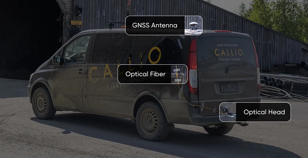
Figure 3: The Mercedes-Benz V-class test vehicle at the mine portal preparing for a test run. The external optical head and GNSS receiver (for external reference when on surface) are visible.
Optical fiber was used to connect the externally mounted LVS optical head to the LVS sensor inside the vehicle. The Boreas D90 along with various additional equipment providing power, networking, and logging capabilities were secured inside the vehicle.
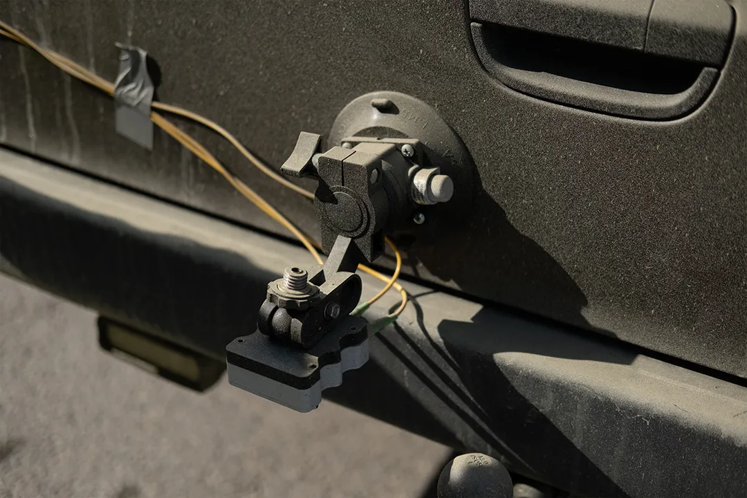

Figure 4: LVS optical head mounted via a suction cup to the trunk of the test vehicle. For best performance, the optical heads need to be rigidly mounted relative to the Boreas INS. In this test, the vehicle frame and chassis were able to provide sufficient rigidity.
The LVS optical head was attached to the trunk of the vehicle using a suction cup, and a GNSS antenna was attached to the roof in the same manner. Coaxial cable connected the GNSS Antenna to the Boreas D90. Optical fiber was routed from the LVS sensor body located in the toolbox to the optical head. Since pre-production hardware was used for this test, three discrete fiber-optic cables were used to connect the optical head to the LVS sensor body. Production hardware will include a single, IP69K rated optical fibre cable that connects the LVS sensor body to the IP69K rated optical head.
The testing at Callio Mine was used to validate the performance of the Hybrid Navigation System (Boreas D90 + LVS) in the absence of GNSS. Two different test scenarios were conducted: a surface-to-surface test, and a completely underground loop test.
The surface-to-surface tests started with a short (~500 m) drive on the surface prior to entering the mine portal. The purpose of this short surface section is to enable the capturing of reference GNSS position fixes, as well as to initialize the INS filter. Once the vehicle entered the tunnel portal the GNSS signal was lost, resulting in the system only being able to use dead-reckoning to provide a position estimate. All filtering was conducted in real-time on board the INS. When inside the tunnel portal, GNSS was disabled from being used by the filter (even though it is not available in the tunnel segments). The vehicle then descended down the incline tunnel to depths of both 400 m and 1400 m, before turning around and ascending.
As the vehicle exited the portal, GNSS signals once again became available and were recorded by the system. Note, however, that since the Internal GNSS Filter option had been disabled, these position measurements were not used by the system, but were instead used as a comparison against the position reference recorded initially. RTK corrections were also applied in real-time to improve the reference position estimates so an accurate performance comparison could be made. The final dead-reckoning position estimate was then compared to the GNSS reference to determine the 3D error.
Figure 5 shows the Hybrid Navigation System’s estimate , as well as the reference RTK GNSS traces at the time the vehicle exits the tunnel portal. While the vehicle exits the tunnel, low quality GNSS measurements are recorded due to multi-path reflections. Once the test vehicle is clear of the tunnel structure, and has clear sky visibility, the GNSS reference converges and can be used to calculate the final position error. The position estimate shown in Figure 5 is a dead-reckoning result. The hybrid system did not use or have access to GNSS measurements even after reaching the surface. The final position error in this trial compared to the reference was 0.55 ±0.09 m.
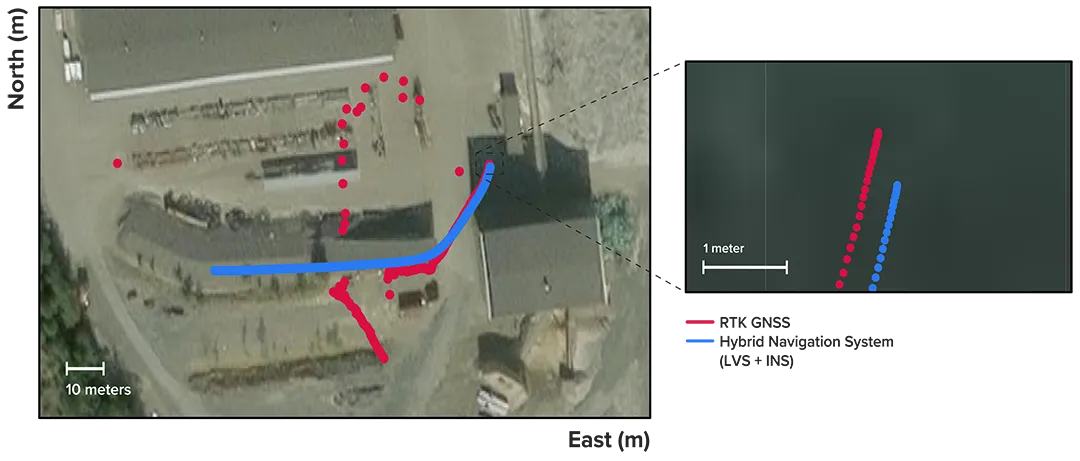
Figure 5: Traces of raw RTK GNSS and position estimates from the Hybrid Navigation System. As the vehicle exits the tunnel portal, intermittent and low accuracy GNSS is measured. Once the vehicle enters open sky, a more consistent RTK GNSS fix is attained. Note that despite the presence of now accurate RTK GNSS, at no point did the Hybrid System use GNSS information.
To further demonstrate the capabilities of our Hybrid Navigation System, an entirely underground circuit was traversed in the test vehicle with zero GNSS locks at all. The test commenced with the vehicle positioned approximately 1100m underground. This test was conducted as a navigation test purely in a local frame of reference – no transform back to the geographic Latitude, Longitude, Altitude (LLA) frame was made. A total station was set up in a tunnel intersection, serving as the datum point for this test.
Position measurements were made from the total station to multiple survey prisms mounted at various locations on the test vehicle. The need for multiple measurements was to ascertain the relative orientation of the test vehicle (and, as such, the relative orientation of the Hybrid Navigation System) to the total station.
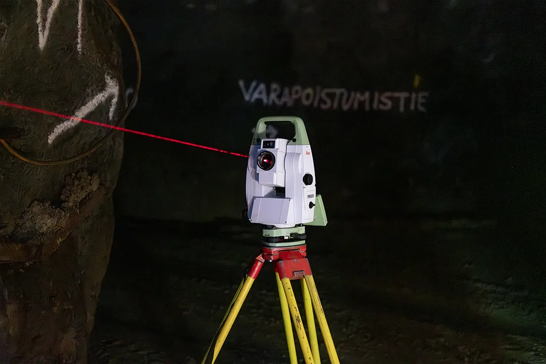
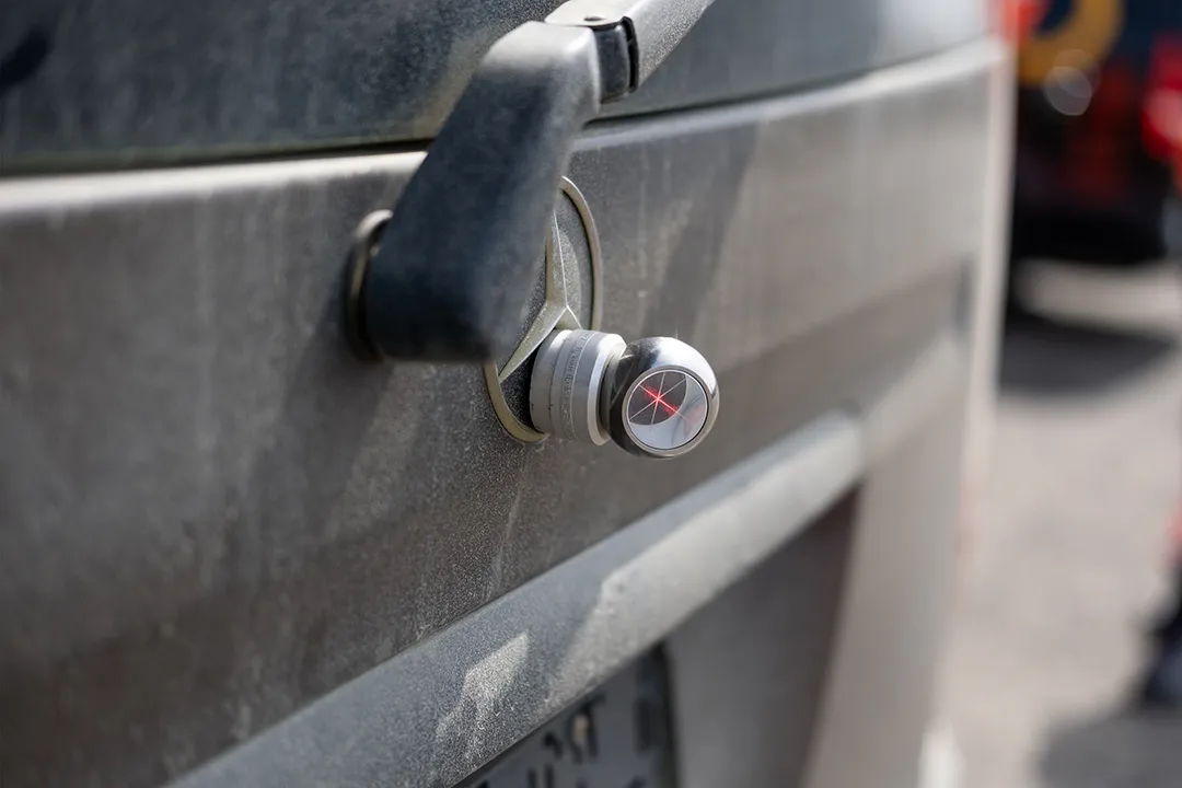
Figure 6: A. Total station used as the datum for the entirely underground tests. B. Multiple survey prisms were attached to the test vehicle in order to ascertain the relative orientation of the test vehicle (and, as such, the relative orientation of the Hybrid Navigation System) to the total station.
Once the initial position measurements were made, the vehicle set off and drove through various tunnels (remaining underground at all times) before returning to the vicinity of the start location. The total station was then used to measure the relative end position and orientation of the vehicle. The difference in position between the measured start and end points were then used to compute the overall performance metrics for these tests.
To demonstrate the system’s repeatability and accuracy, three identical runs were conducted to a depth of 400 meters. The table below presents the key performance metrics for these runs, each involving an approximate 3 km one-way traverse for a full 6 km loop. The results highlight the system’s consistent performance during underground operation, with a mean final position error of 2.83 ±0.09 meters, representing 0.047% of the total distance travelled.
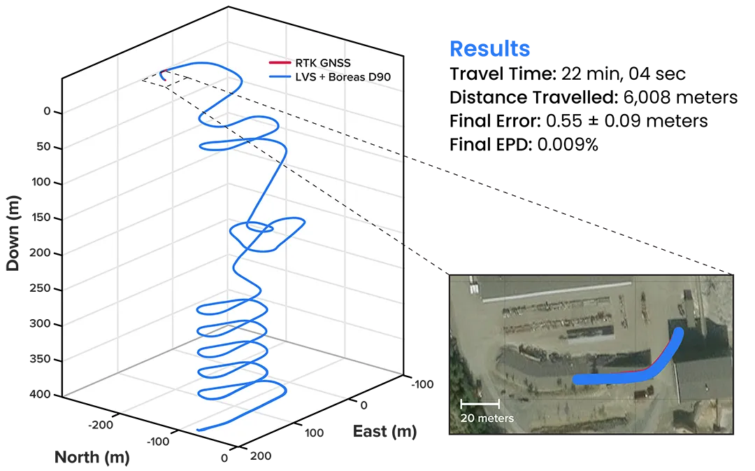
Figure 7: 3D navigation trace of run 2 of the repeat surface-to-surface 400m depth tests. This particular run covered 6008 m, with a measured error of 0.55 ±0.09 m for 0.009% error per distance travelled.

Table 1: Position Error Metrics for 3 Repeat 400m Tests
“We’ve worked in underground environments for decades. Seeing this level of precision achieved on the first run signals huge potential for safer and more efficient underground vehicle operations.”
Olli Mylläri, Vice President Technology at Normet
To evaluate the system’s performance over an extended distance, a single run was conducted to the deepest accessible point of the mine, reaching a depth of 1400 meters. This extended traverse, lasting over 94 minutes, also included a deliberate stationary period at the bottom before the return to the surface. The performance of this deep run is detailed in Figure 8.
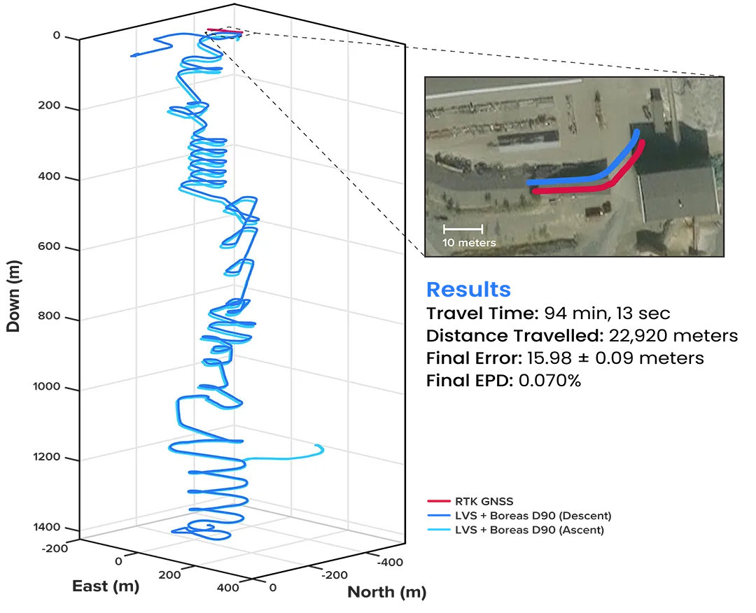
Figure 8: 3D navigation trace of the run down to 1400 m depth. The test traversed a total distance of 22920 m, with a measured final error of 15.98 ±0.09 m yielding an error per distance travelled of 0.070%.
The descent and ascent paths are coloured differently for disambiguation. During the ascent (light blue), the driver entered a side tunnel at a depth of approximately 1200 m which was not traversed on the descent.
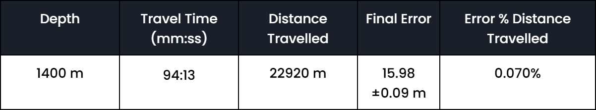
Table 2: Position Error Metrics for 1400m Test
A single run of length 1067 m was conducted over a period of 14 minutes (Figure 9). While additional testing was planned to further validate the results, time constraints limited this study to a single test. Nonetheless, the findings provide a representative indication of system performance under the tested conditions.
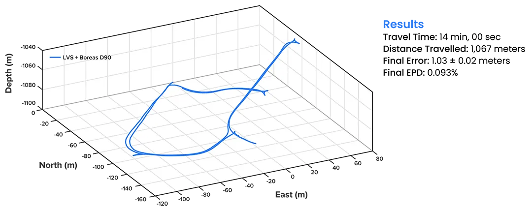
Figure 9: 3D navigation trace of the entirely underground run. The test traversed a total distance of 1067 m, with a measured final error of 1.03 ±0.02 m yielding an error per distance travelled of 0.093%.

Table 3: Position Error Metrics for Underground Initialization Test
These results highlight the ability for the Hybrid Navigation System to maintain precise relative positioning when initialised and operating entirely underground without continuous external aiding.
“We were thoroughly impressed by the results the sensor fusion provided. I have been exposed to these sorts of sensors in other projects, and nothing has come close to this level of performance. It’s clear the Laser Velocity Sensor is a major key in providing these outstanding results.”
Magnus Zetterberg, Senior Consultant, Combitech
Advanced Navigation’s Hybrid Navigation System, combining a high-performance Laser Velocity Sensor (LVS) with the Boreas D90 fiber-optic gyroscope-based Inertial Navigation System (INS), offers a breakthrough in infrastructure-free underground positioning. Demonstrated at the Callio Mine in Pyhäjärvi, Finland, the system delivered consistent dead-reckoning accuracy better than 0.1% of distance travelled across multiple trials. This included a mean final position error of 2.83 meters over three 6 km loops at 400 m depth (0.047%), and 15.98 meters over a 22.9 km traverse at 1400 m depth (0.070%). It also achieved 1.00 m error over a 1067 m fully underground run (0.093%) without any external aiding.
Unlike conventional systems, this solution operates without fixed infrastructure, GNSS, or prior mapping. This enables deployment in previously inaccessible or unmapped zones. While alternative fixed positioning infrastructure exists, such as ultra-wideband, WiFi, 5G, these are often constrained by the need for dense infrastructure or by challenging environmental conditions underground. The Hybrid Navigation System significantly reduces this dependency.
This performance marks a step change in underground navigation, unlocking new potential for fleet management, material tracking and scalable autonomy across underground mining operations.
Advanced Navigation would like to thank the BHP Think & Act Differently division for facilitating this demonstration, Callio Mine for hosting the trials, and Combitech for visualization software. We also extend our thanks to Normet for their advice within the mine.
11 August 2025
Go to Article
20 May 2025
Go to Article