Nextcore/Cordel COO and founder, Ashley Cox shares insights and expertise with Advanced Navigation’s Head of Product, Adam Barnes in integrating INS and LiDAR. Cox discusses his team’s latest UAV LiDAR and rail surveying products and adopting the best GNSS/INS navigation solutions for them.

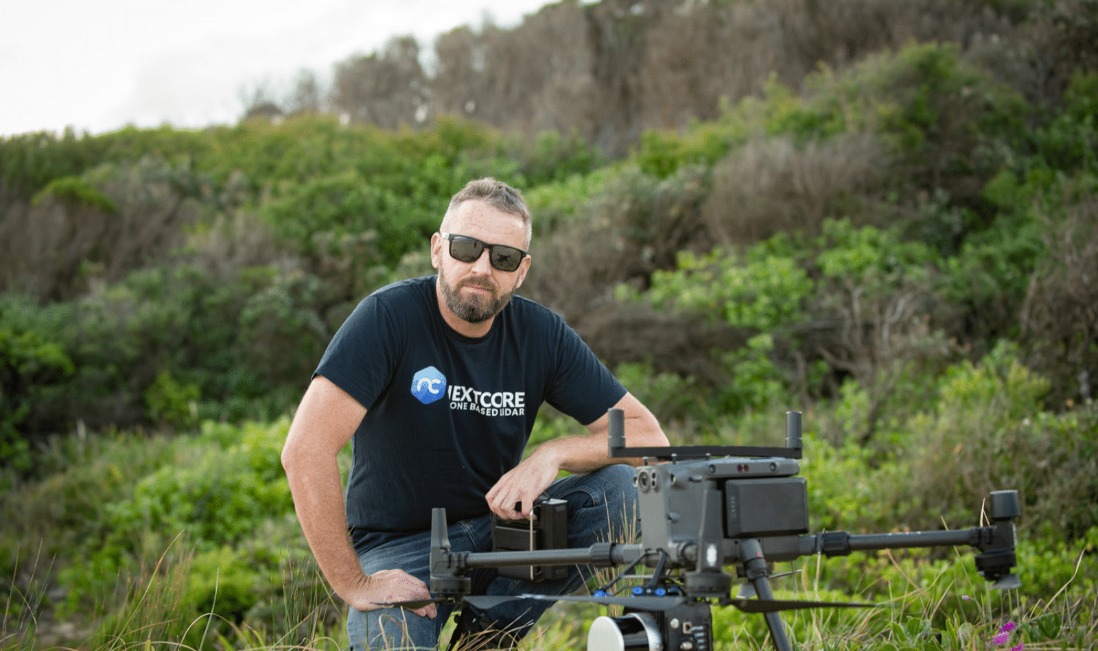
Ashley Cox, COO and founder of Nextcore/Cordel
Ashley began Nextcore as a drone-based aerial surveying business, adopting LiDAR technology into UAVs. The company quickly progressed to developing LiDAR equipment specifically for UAV applications that provides reliable solutions in environments with limited access, dense vegetation, and obstacles such as power lines and difficult terrain.
Cox went on to start Cordel to bring his expertise in integrating INS and LiDAR to the ground for use in rail networks. Their system can be mounted on trains for track and rail corridor surveying, to detect areas requiring track maintenance and track-side foliage reduction, among other applications. More recently, they have applied machine learning to automate the analytics process and provided a range of metrics and data that typically require time-consuming and expensive manual inspection processes and are often disruptive to rail services.
What kind of equipment do you build and operate for UAV LiDAR surveying?
We make systems that can be fitted to commercially available UAV drones that allow our customers to access difficult-to-reach places and quickly and accurately map an area. This is not limited to land surveying but includes widespread applications such as environmental sciences, agriculture, forestry, mining, construction, and utilities. This means that the system must be reliable, lightweight, and rugged.
Using the survey of Tomaree Head (NSW, Australia) as an example, can you provide some input into the process you use?
Our client, the National Parks & Wildlife Service, required a land survey of an area with dense vegetation and steep, rugged terrain that would be very dangerous for human surveyors to operate in. The client needed a high-resolution map to understand what was happening on the ground beneath the vegetation.
Our system allows us to achieve an altitude and fly over the area to perform the survey. The purpose of the survey was for designing safe recreational walkways around the site.
Reducing size and weight for UAV applications is really important. Can you describe your system for us?
The industry is constantly seeking lighter payloads for longer flight times and to be able to fit on smaller, safer UAVs. Our current Lumos system weighs 1.6kg, which enables it to be flown for 30 minutes or more on most modern UAVs.
The key internal component is the laser scanner, however, we need to combine that with location and timing by using a very high-quality INS. We have extensively tested different systems to help achieve the necessary lightweight, accuracy, and reliability. Our previous systems used Advanced Navigation’s Spatial Dual INS. For this latest system, we use the Certus Evo INS in OEM [PCB and chassis only] form. This enables it to be fitted inside our ruggedised casing, further saving weight.
Apart from position and timing from the INS, is there anything else in terms of roll, pitch, and heading that is important for this application?
Logging LiDAR data at millions of points per second from a UAV that is constantly moving X, Y, and Z and making sense of it to create a manageable point cloud is incredibly challenging. If you haven’t collected accurate information about where you are and where you’re going, then you cannot produce a survey-grade point cloud for your client. The more accuracy you can get from your INS, the better you can make sense of the data. Note that processing the data is not something you can do in real-time, so it is a post-flight process.
You use Advanced Navigation Kinematica PPK software as part of your process. Can you briefly describe your workflow, post-flight?
Once the flight is complete, our goal is to get an accurate LiDAR point cloud and make it ready as quickly as possible. Our platform allows us to quickly trim unwanted parts of the mission data, leaving only the actual survey data, which we process by individual flight-line. Using Kinematica further helps our customers achieve a fast turnaround, where they can easily upload data for processing. By the time the customer is back at the office, the data is ready to go.
What do you have to consider regarding UAV elevation and LiDAR point cloud density?
The biggest challenge is maintaining a point cloud density that meets the required resolution. This is usually 200~500 points/m2. UAV has an advantage over manned aircraft in that, at lower altitudes and speed, it is much easier to achieve that resolution. A major problem at low altitude, however, is colliding with trees, power lines, and terrain, for example. Notably, many current UAV LiDAR systems struggle to provide a meaningful point cloud at altitudes above 40~50m.
There is constant pressure from customers to fly higher and still achieve survey-grade outcomes, but with reduced risk of UAV collisions. This made increasing altitude a major priority – we now have systems that provide good point density and can deliver survey-grade resolution at 100m, even 120m, above ground level. This has been vitally important for our customers.
With the altitudes you are reaching, are we approaching the boundaries of MEMS-based INS, and is there room to go higher?
With every additional metre of elevation comes additional error and noise into the point cloud. This means more risk of inaccuracy as you fly higher, and potentially faster, to cover more ground area. Fortunately, most UAV applications will have good access to GNSS to provide basic position data. When integrating INS and LiDAR with an aim for increased precision, we must ensure that both are of an equally high-quality.
UAVs operating at 100~120m AGL is the legal limit in many countries and it’s great to be able to attain this. Additional regulatory controls, such as size and weight, further challenge the UAV surveying industry and can bracket how far development can go. What we have achieved is a real breakthrough. We can reach height limits within a certain budget for our clients and reliably maintain an accurate point cloud. To improve on this really depends on better LiDAR systems and better INS as well.
Do you see VTOL in the future for UAV LiDAR?
Looking ahead at the evolution of UAV LiDAR technology and what might be possible in the future for even faster surveying, VTOL UAV (vertical take-off and landing) is a likely emerging technology.
I think we will be moving to that more quickly, however, regulatory challenges for VTOL systems including altitude, speed, and applicable LiDAR equipment, for what is essentially a lightweight plane, need to be addressed. We have built systems, but the challenge going forward will be handling the altitude and speed and proving the system to be reliable. This will require a step-change in both regulation and technology.
What is the difference in point cloud accuracy, particularly in heavy vegetation, between low altitude UAV LiDAR compared with high altitude plane-based LiDAR?
Standard UAV applications typically aim for <50mm GSD (ground sample distance). Our system can achieve <30mm accuracy in some cases. With planes, the accuracy of LiDAR point data is not in question so much as is the density of the point cloud, due to the aircraft speed. With far fewer points per square metre, vegetation penetration and the ability to map complex terrain are significantly reduced.

The Cordel team testing Advanced Navigation’s Boreas
In terms of your land-based LiDAR surveying, can you describe how you have tested Advanced Navigation’s new Boreas digital FOG INS?
Our key focus for land-based surveying is rail, however, it is incredibly difficult to use the actual rail system for testing INS and LiDAR integration. So, we performed extensive testing using road vehicles, traversing routes in two directions then overlaying the LiDAR maps to check for discrepancies or unsynchronised areas. Our results provided the confidence to put the Boreas into service in actual rail applications.
What are you looking for with a FOG-based INS?
The ability to continue surveying when GNSS is disrupted. In rail, we don’t have the same level of access to GNSS as airborne UAVs. For example, trees over the railway and tunnels, which can be very long. This makes extracting a meaningful path from the system increasingly challenging.
With the Boreas FOG-based system, we can lose GNSS entirely for periods of time without having to worry about trajectory. For this, we need accurate dead reckoning to identify the exact position of the train at the point of GNSS disruption. From which point INS takes over providing position data. The greater the precision of the INS, the easier it becomes to achieve an accurate path.
When you are testing a system like this, how do you measure its accuracy?
Using LiDAR is a great way to actually prove the accuracy of the INS. With our road testing, if the INS is not performing well, the LiDAR data makes it very obvious, very quickly. When you compare the data for each direction you traveled, you are looking for point clouds that are basically identical.
With rail, what are some of the more specific challenges you face?
Rail is a harsh environment and the systems are often in use for years, so ruggedness and total dependability are paramount. You are also operating unmanned, so our systems are completely automated. Each time a train starts, the system needs to boot up and tell us that it’s scanning correctly. The train may be in the US, for example, and we are watching the system collecting data in Australia.
On top of that, you are going to face GNSS disruption at some point, and you need to be able to show clients that you can still understand what is going on in their rail environment.

The Boreas FOG used on a train
Is speed a factor for you choosing a *FOG INS over *MEMS INS?
Absolutely. We must be completely comfortable operating at speeds of 160km/h (100mph), which is a typical requirement. This is basically out of scope for MEMS-based INS. Thinking about the future and very high-speed rail, such as mag-lev, we will need to be able to cope in those environments and deliver reliability.
Can you describe some of the practical elements that you want to achieve in rail LiDAR scanning?
Effectively, we are automating a great deal of rail corridor inspection requirements. The scanning trajectory of the LiDAR is “tuned” to suit the required rail metrics. For example, identifying areas where vegetation is getting too close to the train, where there is excess or insufficient track ballast, and accurately measuring alignment and distance between the rails.
We basically automate the ticketing process to flag locations where any of the metrics we are scanning for are out of specification. The net result is a “google map” of the track, with clearly marked points of interest. When the client selects an area, they can view the LiDAR scan (and video, if applicable) to get a clear picture of the issues and how to respond before sending personnel to the location.
*FOG (fiber-optic gyroscope) and MEMS (micro-electromechanical systems) are INS technologies that suit different applications. FOG typically provides greater accuracy than MEMS, however, comes with increased cost, size, and weight.